System And Method For Converting Fluid Motion Into Electrical Power

a technology of fluid motion and electrical power, applied in the control system, electrical equipment, electrical generator control, etc., can solve the problems of water turbines that require very selective placement, water turbines that typically require placement, and the energy in moving that mass of water every day is absolutely enormous

Active Publication Date: 2013-11-14
THE BOEING CO
View PDF8 Cites 10 Cited by
  • Summary
  • Abstract
  • Description
  • Claims
  • Application Information

AI Technical Summary

Benefits of technology

[0006]Examples the present disclosure are generally directed to a system and method for converting fluid motion into electrical power. Compared water turbines that typically require significant current flow, the system and method may be used in a number of current or velocity environments. In this regard, compared water turbines that typically require significant current flow, the system and method may be used in low current or other low velocity environments. Examples may further provide multiple configurations for different phases of a power cycle, and / or an increased number of degrees of freedom to account for fluid motion in different directions.

Problems solved by technology

The energy in moving that mass of water every day is absolutely enormous.
Similar to wind turbines, however, water turbines require very selective placement to yield sufficient power.
That is, water turbines typically require placement in areas of significant current flow.
Water turbines are also often large, complex, bulky devices that are not easily deployed.
Water turbines also often require an undesirable amount of time to deploy.
For forward operating base (FOB) and similar applications that may benefit from water-based energy production, speed of deployment as well as the flexibility of deployment in a wide variety of situations may be significant issues.

Method used


Image

  • System And Method For Converting Fluid Motion Into Electrical Power
  • System And Method For Converting Fluid Motion Into Electrical Power
  • System And Method For Converting Fluid Motion Into Electrical Power

Examples


Embodiment Construction

[0024]Some embodiments of the present disclosure will now be described more fully hereinafter with reference to the accompanying drawings, in which some, but not all variations of the disclosure are shown. Indeed, variations of the disclosure may be embodied in many different forms and should not be construed as limited to the examples set forth herein; rather, these are provided so that this disclosure will be thorough and complete, and will fully convey the scope of the disclosure to those skilled in the art. Examples may be described with reference to converting underwater current into electrical power, such as in the context of ocean, river or stream current. It should be understood, however, that examples may be equally applicable to the conversion of other fluid movement into electrical power. Like reference numerals refer to like elements throughout.

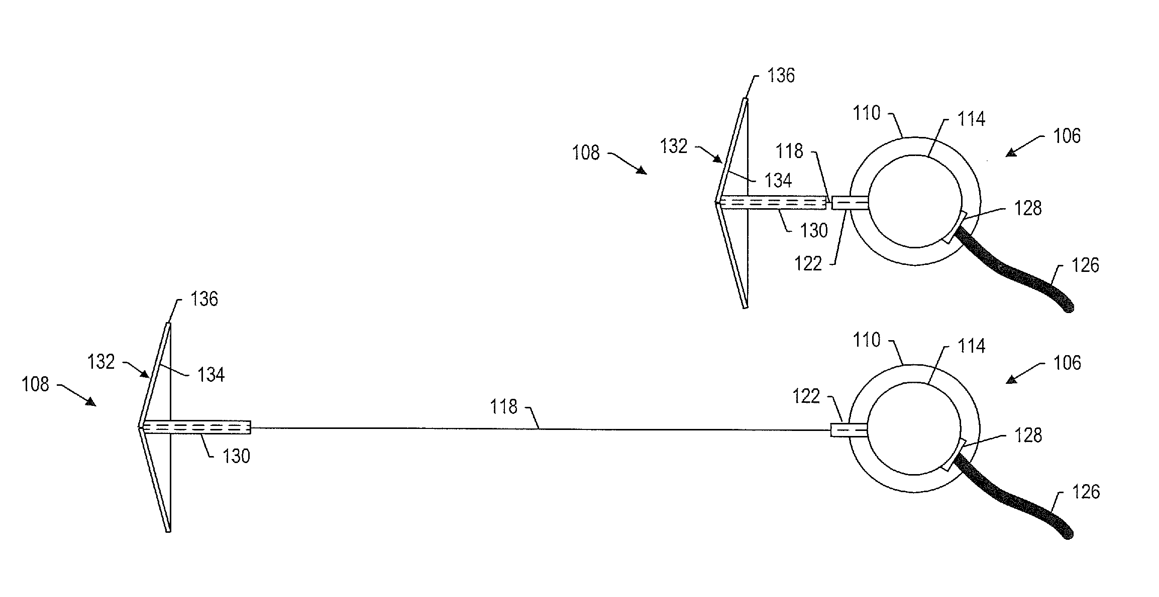
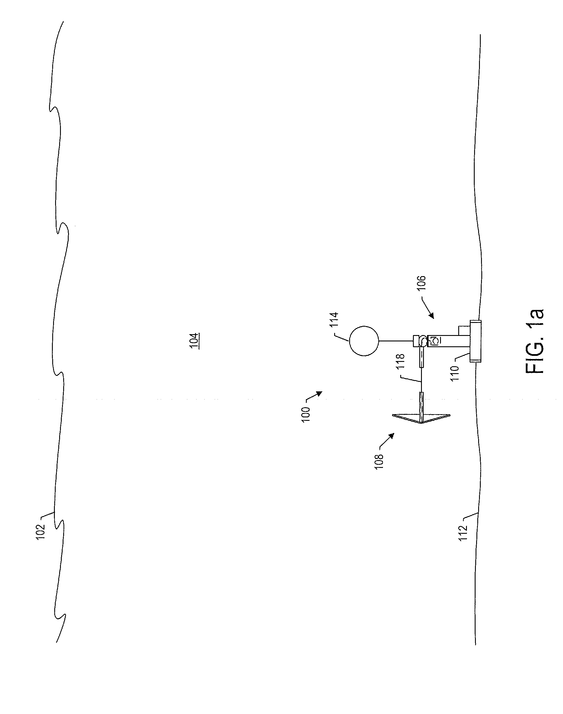
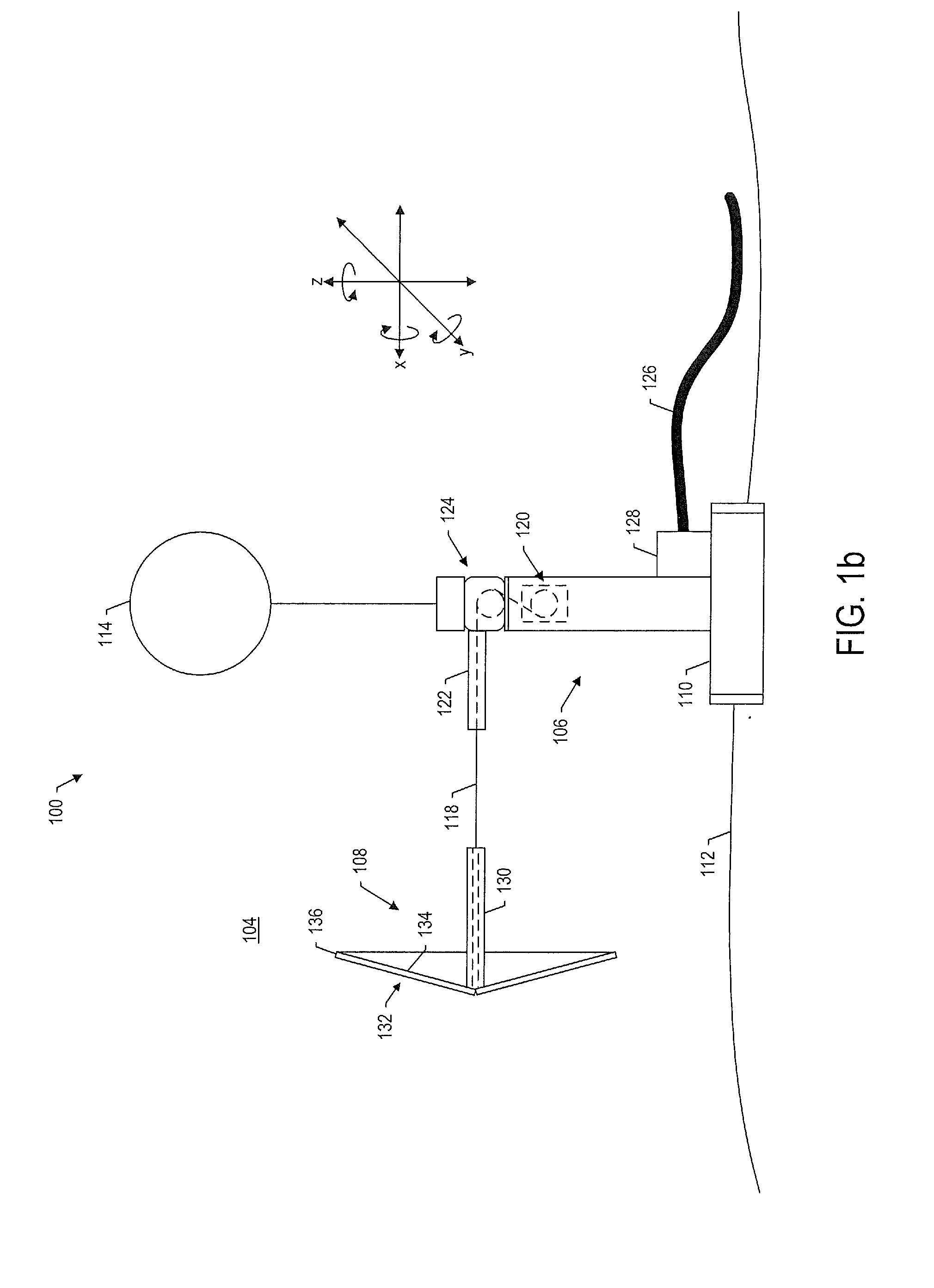
[0025]FIG. 1 illustrates a system 100 according to one example of the present disclosure. As shown, in one example, the system m...


PUM


Abstract

A system is provided for converting fluid motion into electrical power, with the system being deployable in a body of fluid. The system includes a support structure and a movable structure connected to the support structure. The support structure includes a generator assembly configured to convert mechanical energy to electrical energy and provide electric power from the electrical energy. The movable structure has three or more degrees of freedom, and is configured to generate mechanical energy for conversion by the generator assembly during a power generation phase of a power cycle in which the fluid motion acts on the movable structure. The movable structure has a first configuration during the power generation phase and a second, different configuration during a recovery phase of the power cycle, with the movable structure in the first configuration having a greater surface area normal to the flow of fluid.

Description

TECHNOLOGICAL FIELD[0001]The present disclosure relates generally to converting fluid motion into electrical power and, in particular, to a system including reconfigurable movable structure that converts underwater current into electrical power.BACKGROUND[0002]There is a pressing need to develop clean energy sources. Since most of the surface of the earth is covered by water, water-based systems provide the most potential for energy generation due to sheer volume. The gravitational effect that causes tides provides an enormous amount of energy since the mass and force of the water is many times greater than that of any air-based system. Moving even just a few thousand cubic feet of water requires energy that would take up incredible amounts of airspace or physical land to be equaled with either wind or solar power. Therefore the tides may provide a significant amount of renewable energy to be harnessed by orders of magnitude over other renewable energy forms.[0003]As an example, the...

Claims


Application Information

Patent Timeline
Patent Type & Authority Applications(United States)
IPC IPC(8): F03B13/10
CPCF03B13/264F03B17/06F05B2240/311F05B2250/43Y02E10/20Y02E10/30
Inventor GRUBEL, BRIAN C.
Owner THE BOEING CO
Why Eureka
Try Eureka