Method and apparatus for generating electron beams

a technology of electron beams and electron beams, which is applied in the direction of cathode ray tubes/electron beam tubes, additive manufacturing processes, electric discharge tubes, etc., can solve the problems of difficult to form a usable electron beam for freeform fabrication, difficult to say impossible to switch the electron, and limited switching frequency, so as to achieve the effect of reducing the leakage of electron beams through the exit hole, increasing beam power, and reducing the leakage ra

Inactive Publication Date: 2013-11-14
ARCAM AB
View PDF4 Cites 158 Cited by
  • Summary
  • Abstract
  • Description
  • Claims
  • Application Information

AI Technical Summary

Benefits of technology

[0018]In certain embodiments, such parameters comprise means for plasma confinement within the cathode discharge chamber. By providing the means for plasma confinement within the cathode discharge chamber and switching the means between a confining and a non-confining state for achieving pulsed electron beam will give a fast control of the pulsed electron beam.
[0021]The advantage of this embodiment is that it provides an easy control of beam power without interfering with the beam quality, i.e., good focus and intensity stability over space and time. The varying of the duty cycle of the first value of the plasma confinement provides for a very efficient means for beam power adjustment. The beam power may be switched between two different power levels in the order of as fast as the control mechanism may change the duty cycle of the first value of the current through the at least one means for plasma confinement. The plasma may be created, destroyed and / or reshaped very quickly.
[0023]The advantage of such embodiments is that the plasma generation is separate and independent from the switching coil. Another advantage is that the electromagnetic wave source is an effective means for plasma generation.
[0026]In still other exemplary embodiments, at least one electron beam controlling plate 125 provided inside the cathode discharge chamber 100 and arranged so that at least a part of the plasma is provided between the electron beam controlling plate 125 and the exit hole 120. An advantage of such embodiments is that it provides for additional control of electron emission. Another advantage of the embodiment is that it provides for increased beam power. Still another advantage is that the electron beam leakage through the exit hole may be completely reduced. Still another advantage is that the at least one electron beam controlling plate is an effective means for plasma generation.
[0027]In still other exemplary embodiments, the electromagnetic coil 103 is substituted by at least one electron beam controlling plate 125 provided inside the cathode discharge chamber 100 and arranged so that at least a part of the plasma is provided between the electron beam controlling plate 125 and the exit hole 120. An advantage of such embodiments is that it is simpler than with a coil for forcing the electron through the exit hole.

Problems solved by technology

It is difficult for not saying impossible to switch the electron generation from a hot filament on and off faster than 50 Hz.
However, with a triod design it may be difficult to form a usable electron beam for freeform fabrication with good quality with respect to focus and intensity stability over space and time and for variable current.
When an electron beam is generated from a plasma source the switching frequency is limited by the time for creating a plasma and extinguish a plasma.
It is also limited by the switching time for the high voltage needed for turning on and off the plasma.
The highest possible plasma generating frequency is in theory about 10 MHz, but in practice limited by the switching time of the high voltage drive electronics.
The known methods for creating pulsed electron beams do not have a sufficiently high pulse rate without influencing electron beam quality, which may be a problem in additive manufacturing.

Method used


Image

  • Method and apparatus for generating electron beams
  • Method and apparatus for generating electron beams
  • Method and apparatus for generating electron beams

Examples


Embodiment Construction

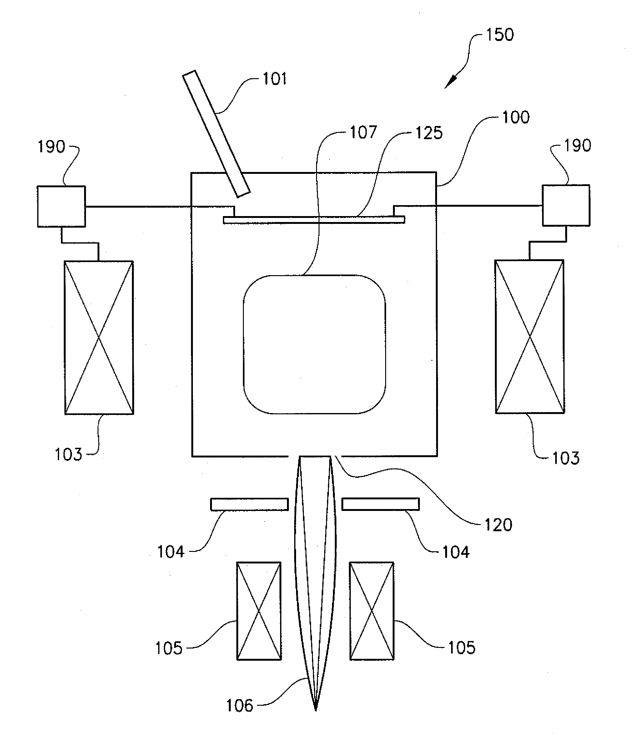
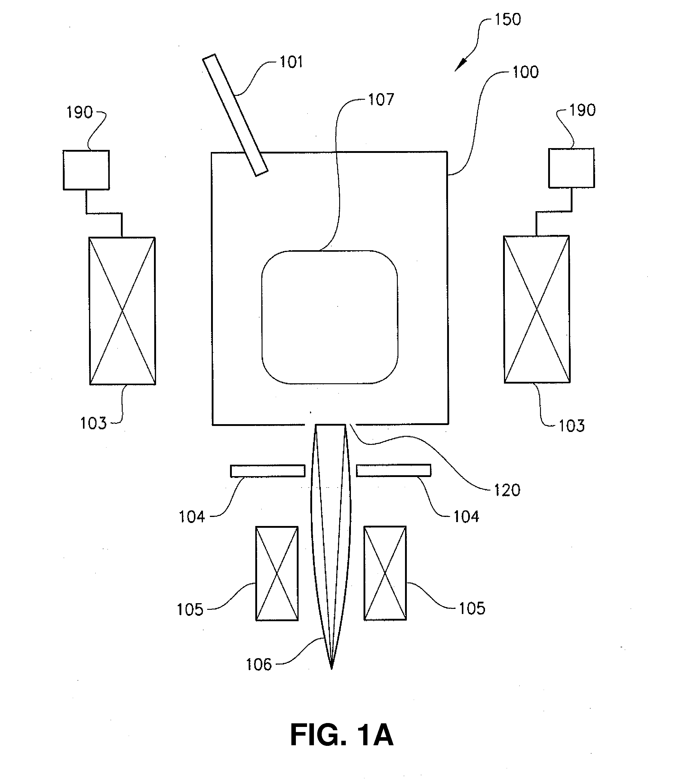
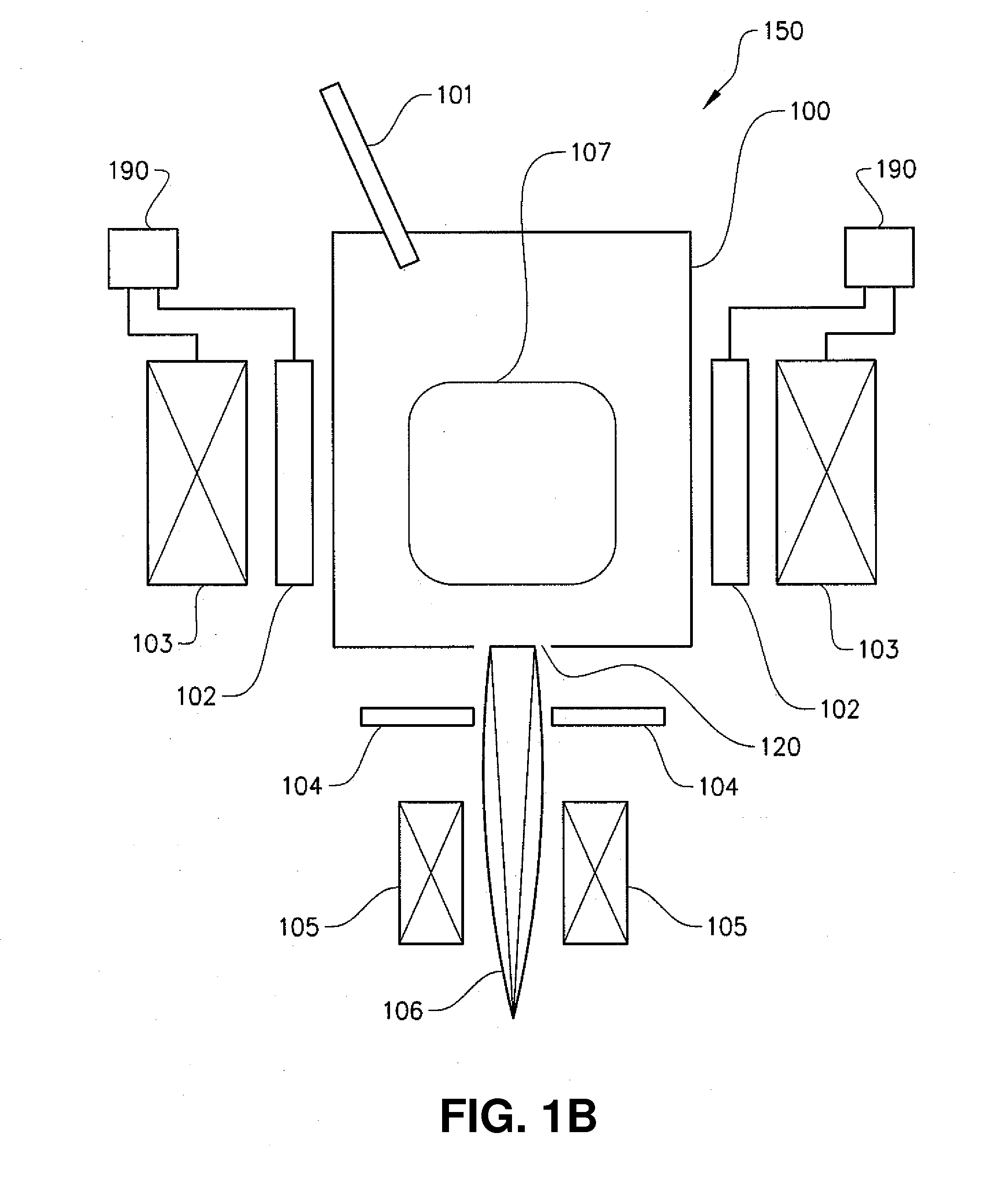
[0041]Various embodiments will now be described more fully hereinafter with reference to the accompanying drawings, in which some, but not all embodiments of the inventions are shown. Indeed, the various embodiments of the present invention may be embodied in many different forms and should not be construed as limited to the embodiments set forth herein; rather, these embodiments are provided so that this disclosure will satisfy applicable legal requirements.

[0042]To facilitate the understanding of this invention, a number of terms are defined below. Terms defined herein have meanings as commonly understood by a person of ordinary skill in the areas relevant to the present invention. Terms such as “a”, “an” and “the” are not intended to refer to only a singular entity, but include the general class of which a specific example may be used for illustration. The terminology herein is used to describe specific embodiments of the invention, but their usage does not delimit the invention,...


PUM


Abstract

Various embodiments of the present invention relate to a plasma electron source apparatus. The apparatus comprises a cathode discharge chamber in which a plasma is generated, an exit hole provided in said cathode discharge chamber from which electrons from the plasma are extracted by an accelerating field provided between said cathode discharge chamber and an anode, at least one plasma confinement device, and a switching mechanism for switching the at least one plasma confinement device between a first value allowing for electron extraction from the plasma and a second value prohibiting electron extraction from the plasma. Associated methods are also provided.

Description

CROSS-REFERENCE TO RELATED APPLICATIONS[0001]This application claims priority to and the benefit of U.S. Provisional Application Ser. No. 61 / 644,513, filed May 9, 2012, the contents of which are hereby incorporated by reference in its entirety.BACKGROUND[0002]1. Field of the Invention[0003]Various embodiments of the present invention relate to a plasma electron source apparatus, a method for generating pulsed electron beams and the use of a plasma electron source apparatus.[0004]2. Description of Related Art[0005]Freeform fabrication or additive manufacturing is a method for forming three-dimensional articles through successive fusion of chosen parts of powder layers applied to a worktable. A method and apparatus according to this technique is disclosed in US Patent Application Publication No. 2009 / 0152771.[0006]Such an apparatus may comprise a work table on which the three-dimensional article is to be formed, a powder dispenser, arranged to lay down a thin layer of powder on the wo...

Claims


Application Information

Patent Timeline
Patent Type & Authority Applications(United States)
IPC IPC(8): H01J29/52
CPCH01J29/52B29C64/153H01J37/077H01J37/305H01J37/3178H01J2237/043H01J2237/3128H01J2237/31732B33Y10/00B33Y30/00
Inventor LJUNGBLAD, ULRICSVENSSON, MATTIAS
Owner ARCAM AB
Why Eureka
Try Eureka