Electric storage device management system, electric storage device pack, and method of estimating state of charge

a technology of electric storage devices and management systems, applied in the direction of electrochemical generators, battery/fuel cell control arrangements, instruments, etc., can solve the problems of large difference between the soc obtained by the method of estimating an soc, the ocv and the actual so

Active Publication Date: 2013-11-14
GS YUASA INT LTD
View PDF2 Cites 57 Cited by
  • Summary
  • Abstract
  • Description
  • Claims
  • Application Information

AI Technical Summary

Benefits of technology

[0007]The following presents a simplified summary of the invention disclosed herein in order to provide a basic understanding of some aspects of the invention. This summary is not an extensive overview of the invention. It is intended to neither identify key or critical elements of the invention nor delineate the scope of the invention. Its sole purpose is to present some concepts of the invention in a simplified form as a prelude to the more detailed description that is presented later.
[0008]An electric storage device management system described herein includes a voltage sensor, a memory, and a controller. The voltage sensor is configured to detect a voltage across an electric storage device having a correlation between an open circuit voltage (OCV) relative to a state of charge (SOC) includes a slight change region and a sharp change region. The slight change region

Problems solved by technology

Especially, if the electric storage devices include an electrode that is made of material having OCV-SOC characteristic in that a slight change r

Method used


Image

  • Electric storage device management system, electric storage device pack, and method of estimating state of charge
  • Electric storage device management system, electric storage device pack, and method of estimating state of charge
  • Electric storage device management system, electric storage device pack, and method of estimating state of charge

Examples


Embodiment Construction

Overview of this Embodiment

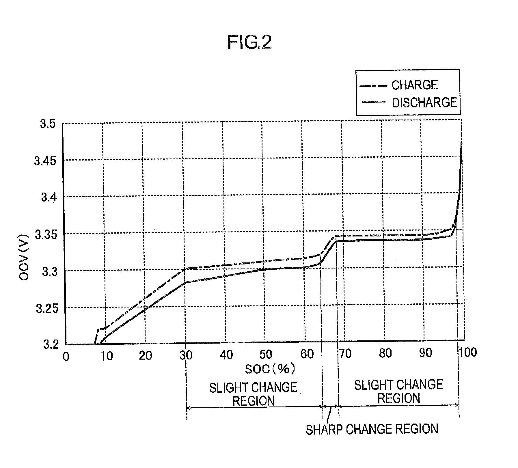
[0015]In a correlation between OCV and SOC of the present electric storage device that is to be under the management of an electric storage device management system, a slight change region and a sharp change region exist. In the slight change region, a change in OCV relative to the SOC is equal to or smaller than a reference value. In the sharp change region, the change is larger than the reference value. According to a configuration of this embodiment, if it is determined that the defined OCV is within the sharp change region, the SOC corresponding to the defined OCV is determined as an estimated SOC based on information on the correlation between the OCV in the sharp change region and the SOC. If it is determined that the defined OCV is out of the sharp change region, the determining of the SOC corresponding to the defined OCV as an estimated SOC is prohibited. With this configuration, determination of an SOC obtained by the method of estimating an SOC u...


PUM


Abstract

An electric storage device management system includes a voltage sensor, a memory, and a controller. The voltage sensor detects a voltage across an electric storage device having a correlation between an open circuit voltage (OCV) and a state of charge (SOC) including a slight change region and a sharp change region. The memory stores information on correlation between OCV and SOC in the sharp change region. The controller is configured to: determine an OCV based on a voltage detected by the voltage sensor; determine whether the defined OCV is within the sharp change region; determine an SOC corresponding to the defined OCV based on the stored information stored if the defined OCV is within the sharp change region; determine the determined SOC as an estimated SOC; and prohibit the determining of the SOC as an estimated SOC if the defined OCV is out of the sharp change region.

Description

CROSS-REFERENCE TO RELATED APPLICATIONS[0001]This application claims priority from Japanese Patent Applications No. 2012-108385 filed on May 10, 2012, No. 2013-053889 filed on Mar. 15, 2013, and No. 2013-082992 filed on Apr. 11, 2013.FIELD[0002]The present invention described in this specification relates to a technology for estimating a state of charge (SOC), or a remaining capacity, of an electric storage device.BACKGROUND[0003]Conventionally, a method for estimating an SOC using an open circuit voltage (OCV) of a cell has been known as an example of a method for estimating an SOC of an electric storage device. In this method, the OCV of the cell is defined, an SOC corresponding to the defined OCV is determined with reference to a predetermined correlation between OCV and SOC, and the determined SOC is determined as an estimated SOC (see Patent Document 1).[0004]Patent Document 1: JP-A-2007-171205[0005]In some electric storage devices, the correlation between OCV and SOC may not b...

Claims


Application Information

Patent Timeline
IPC IPC(8): G01R31/36
CPCG01R31/3606G01R31/388G01R31/367H01M10/48B60L58/16G01R31/3835H02J7/007184Y02T10/70Y02E60/10G01R31/382H02J7/35
Inventor SHIRAISHI, TAKEYUKIITAGAKI, TAKESHI
Owner GS YUASA INT LTD
Why Eureka
Try Eureka