Method and apparatus for generating dedicated data channels in backscatter RFID systems using band-pass modulation

Active Publication Date: 2013-11-14
DRNC HLDG INC
View PDF0 Cites 21 Cited by
  • Summary
  • Abstract
  • Description
  • Claims
  • Application Information

AI Technical Summary

Benefits of technology

The patent describes an antenna apparatus that can backscatter an incoming radio frequency (RF) signal based on its reflection coefficient. The apparatus includes an antenna, a variable impedance circuit, and a band-pass delta sigma (ΔΣ) modulator. The reflection coefficient of the antenna is adjusted based on the digitally controlled output of the variable impedance circuit. The antenna apparatus may be used in a RFID system and may be clocked using a clock circuit within the tag terminal or using a carrier signal frequency of the reader device. The invention allows for efficient and flexible backscattering of RF signals and improves the reliability and accuracy of RFID systems.

Problems solved by technology

As a consequence, tag collision in RFID systems occur when the multiple tags are energized by the same RFID reader device, and simultaneously reflect their respective, overlapping signals back to the reader using the given frequency channel.
Thus the tag collision problem is exacerbated whenever a large number of tags must be read together in the same RF field.
The tag collisions confuse the reader, generate data transmission errors, and generally reduce data throughput within the RFID system or network.
Since each tag gets a unique number interval, the tags send their data at different times. The adverse impact on overall RFID system performance, in terms of data throughput rate, however, still exists.
However, the adverse effects of tag collisions resulting from overlapping backscattered signals on a given frequency channel still remain.
Moreover, especially pertinent in the context of high frequency RF signals is the effect of the DC offset in the reader device and the effects of the reader's phase noise.
The design of backscattering tag terminals in RFID networks involves some further special challenges.
The resulting large swings in the mixer output are harder to filter out, and make it hard to see any reflection from the tag until the receiver has had a few microseconds to recover.
However, the use of a pair of antennas adds cost, complexity, and increased space requirements to the reader.
An adaptive antenna tuner or nuller to reduce the reflections from a single (monostatic) antenna may alternatively be used, but this solution again involves added expense and complexity.

Method used


Image

  • Method and apparatus for generating dedicated data channels in backscatter RFID systems using band-pass modulation
  • Method and apparatus for generating dedicated data channels in backscatter RFID systems using band-pass modulation
  • Method and apparatus for generating dedicated data channels in backscatter RFID systems using band-pass modulation

Examples


Embodiment Construction

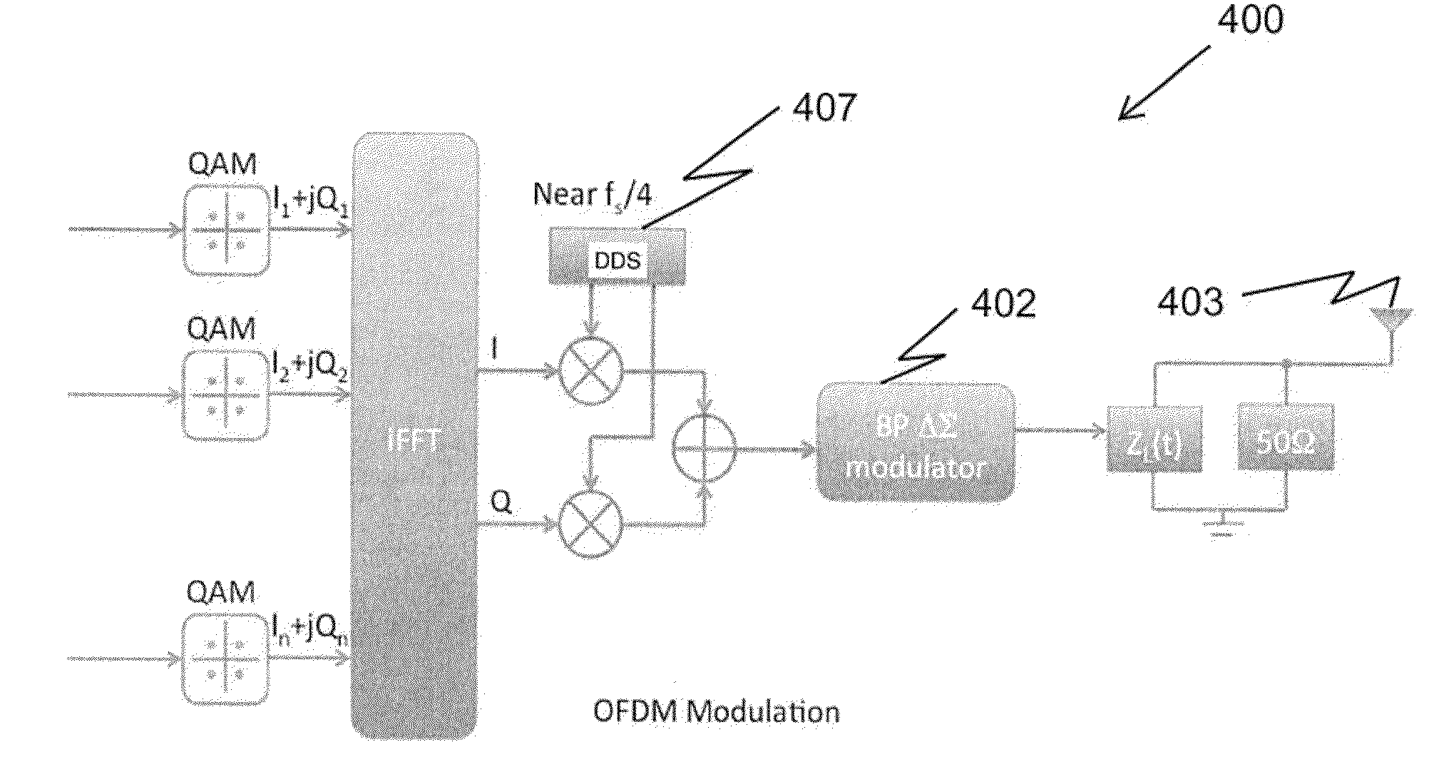
[0033]The term modulation as used herein refers to the process by which the radio frequency identification (RFID) wireless terminal, or tag, changes the carrier radio frequency (RF) signal of the reader antenna to convey information. For instance, in phase modulation, data being transmitted from the reader device to the tag is encoded in changes in the phase of the carrier wave sent out by the RFID reader device.

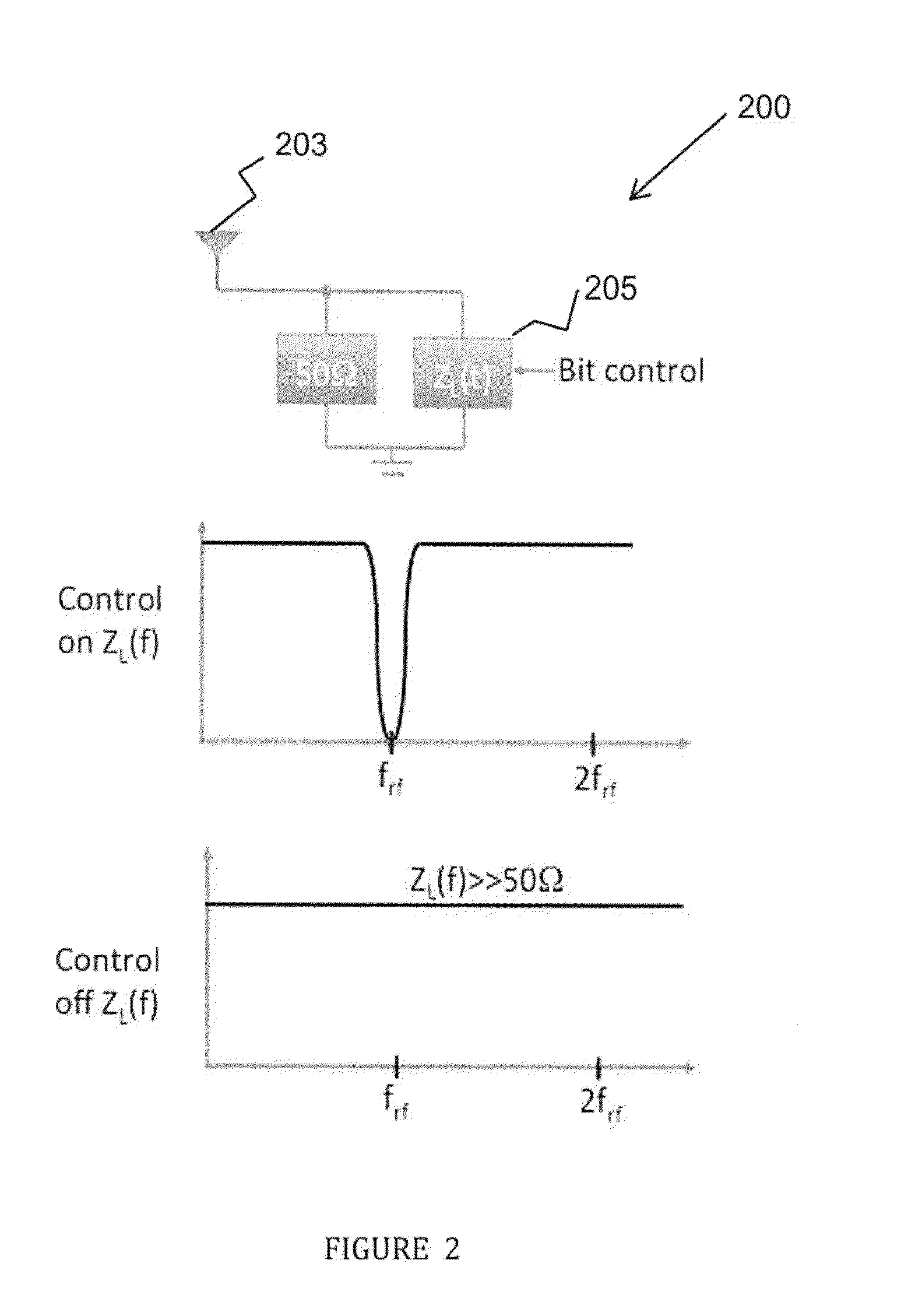
[0034]FIG. 2 shows, in one embodiment, an antenna apparatus 200 in a wireless communication system, such as a radio frequency identification (RFID) communication network, which may be passive or semi-passive, for generating a varying impedance 205 at antenna 203 for backscattering an incoming radio frequency (RF) signal, such as from a reader device of the RFID network. Antenna 203, which may be part a tag terminal of the RFID communication network, backscatters the incoming reader device, or carrier, RF signal in accordance with its reflection coefficient (Γ) characteristic...


PUM


Abstract

An antenna apparatus for backscattering an incoming radio frequency (RF) signal includes an antenna for backscattering the incoming RF signal in accordance with a reflection coefficient characteristic of the antenna. A variable impedance circuit includes an output electrically connected to the antenna. A band-pass delta sigma modulator is coupled to the variable impedance circuit and digitally controls the output of the variable impedance circuit, such that the reflection coefficient of the antenna is adjusted based on the digitally controlled output of the variable impedance circuit. In an RFID network, the apparatus and method reduces the effect of DC offset in the reader device and the effects of the reader device's phase noise, while allowing for complex modulations.

Description

FIELD OF THE INVENTION[0001]The present invention relates generally to a method and apparatus for generating dedicated data transmission channels in backscatter radio frequency communication networks using band-pass signal modulation.BACKGROUND OF THE INVENTION[0002]Radio Frequency Identification (RFID) systems are commonly used to locate and track items in a near-field communication network including a reader device and at least one wireless terminal, or tag. Energized time-varying electromagnetic radio frequency (RF) waves, which comprise the carrier signal, are transmitted from the reader to the tags in a given RFID network or system. Tags use backscatter technology to reflect the reader's RF signal back to the reader, modulating the signal to encode and transmit data.[0003]FIG. 1 depicts a prior art RFID system in which data transmission from tags 101a-c to reader device 103 is performed on a same frequency channel or spectrum 104. Using the established backscattering technology...

Claims


Application Information

Patent Timeline
IPC IPC(8): H01Q9/00H01Q1/50
CPCG01S13/756G06K19/0723G06K19/0726G06K19/07786H04B1/59H04B7/005H04L27/34
Inventor MANKU, TAJINDER
Owner DRNC HLDG INC
Why Eureka
Try Eureka