Air supply and exhaust structure for fuel cell

a fuel cell and air supply technology, applied in the field of air supply and exhaust structure of fuel cells, can solve the problems of deteriorating complicated structure, and negative effect of mounting the fuel cell system to the vehicle, and achieve the effect of enhancing the starting performance of the fuel cell

Active Publication Date: 2013-11-14
SUZUKI MOTOR CORP
View PDF18 Cites 16 Cited by
  • Summary
  • Abstract
  • Description
  • Claims
  • Application Information

AI Technical Summary

Benefits of technology

[0007]The present invention was conceived in consideration of the circumstances encountered in the prior art mentioned above and an object of the present invention is to provide an air ...

Problems solved by technology

However, at the time of low temperature such as in winter and other occasions, the fuel cell is put in a supercooled state, which may deteriorate starting performance of the fuel cell.
However, in the technologies in Patent Documents 1 and 2, it is require...

Method used


Image

  • Air supply and exhaust structure for fuel cell
  • Air supply and exhaust structure for fuel cell
  • Air supply and exhaust structure for fuel cell

Examples


first embodiment

FIGS. 1 to 5

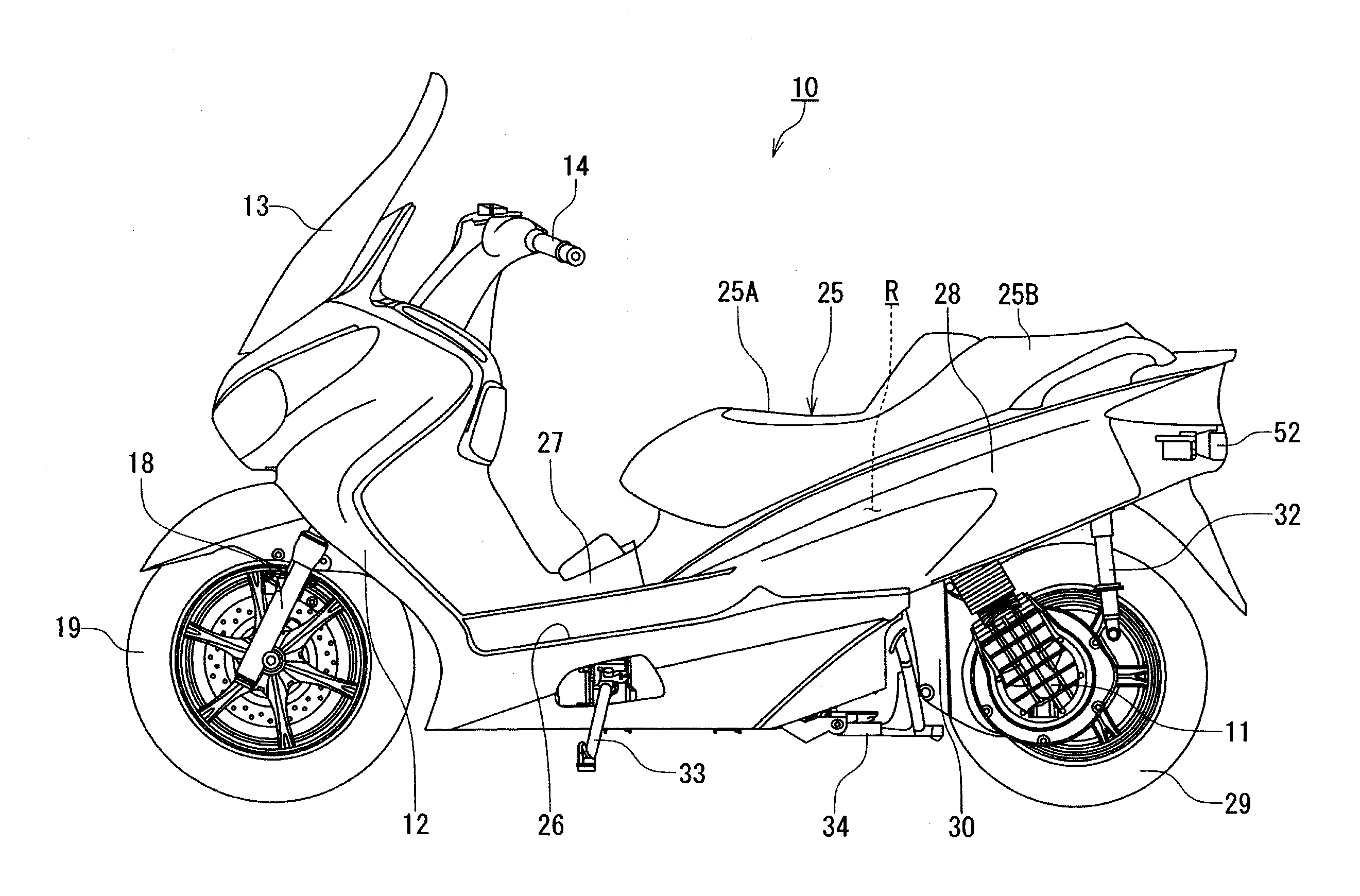
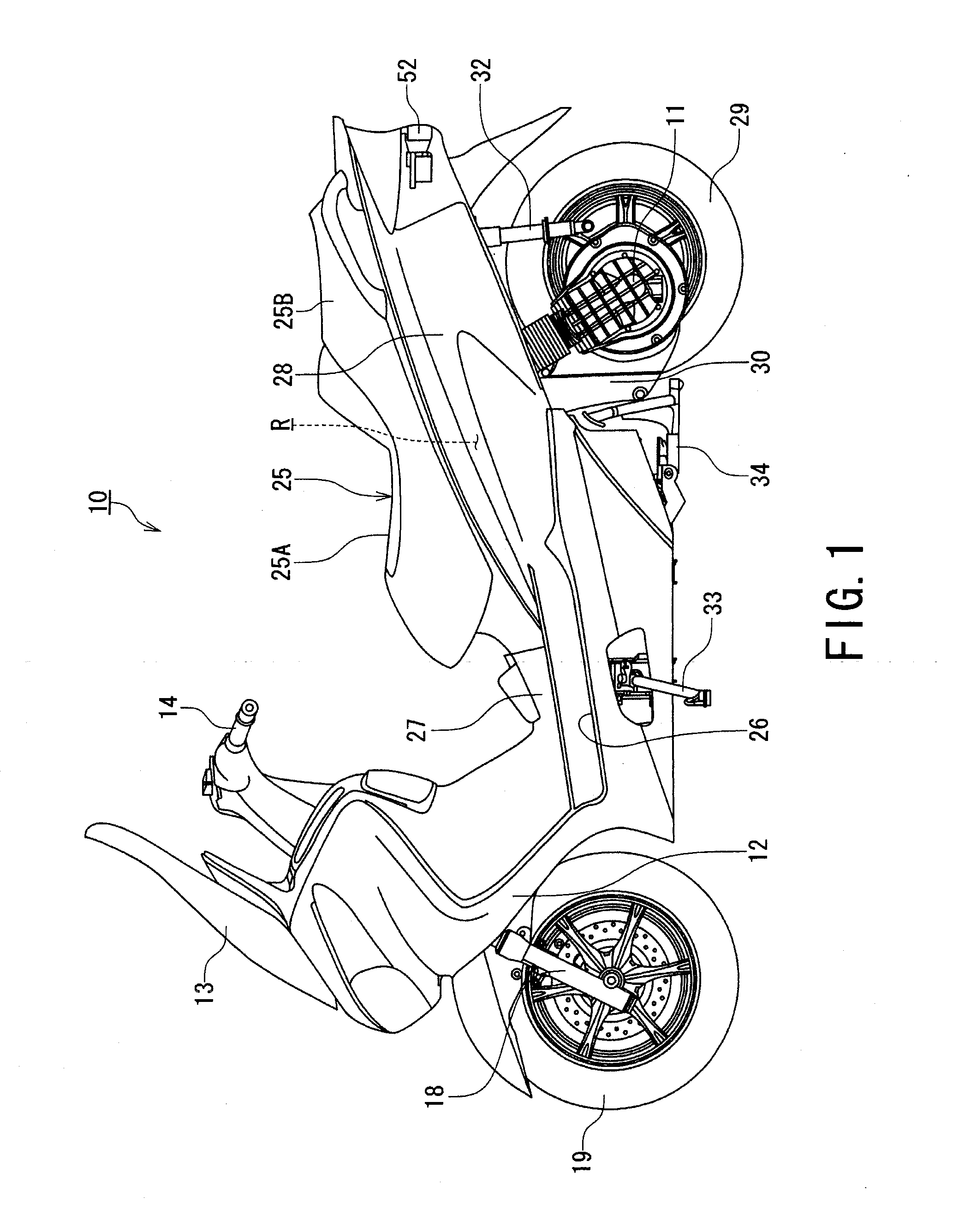
[0028]With reference to FIG. 1, a scooter type motorcycle 10 as a small-size vehicle of this embodiment is a fuel cell mounted vehicle which is driven by rotating a motor 11 with use of electric power obtained from a later-described fuel cell drive system 40 (FIG. 2).

[0029]The scooter type motorcycle 10 includes a leg shield 12, a screen 13, and a handle bar 14 which protrude in a left-right (lateral) direction in a front part of the vehicle as shown in FIG. 1.

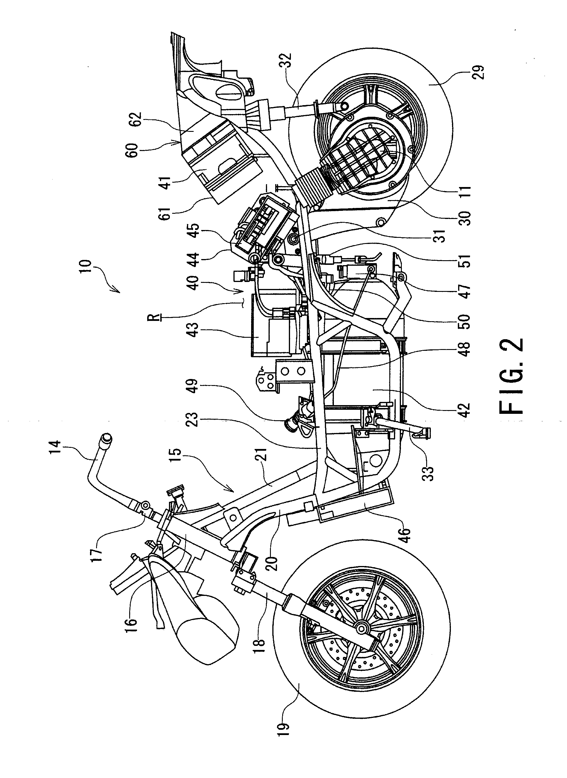
[0030]The handle bar 14 is connected so as to be integrally rotated with a steering shaft 17 that is pivotably supported by a head pipe 16 of a vehicle body frame 15 shown in FIG. 2. A front wheel 19 is suspended on the steering shaft 17 via a pair of left and right front forks 18. Since the steering shaft 17 is pivotably supported by the head pipe 16 so as to be able to rotate in the left-right direction, the front wheel 19 is rotated in the left-right direction by handling of the handle bar 14.

[0031]The vehicle b...

second embodiment

FIGS. 6 to 8

[0076]FIG. 6 is a plan view representing a second embodiment in the air supply and exhaust structure for a fuel cell according to the present invention during normal operation, and FIGS. 7A and 7B are plan views showing the air supply and exhaust structure for a fuel cell shown in FIG. 6, in which FIG. 7A shows a first pattern during low-temperature start and FIG. 7B shows a second pattern during low-temperature start.

[0077]Further, in the second embodiment, component members identical to those in the first embodiment are denoted by identical reference numerals to simplify or omit a duplicated description thereof.

[0078]An air supply and exhaust structure for a fuel cell 70 in the second embodiment is different from the first embodiment in the following points.

[0079]That is, at the time of, for example, low-temperature start of the fuel cell 41 when the fuel cell 41 is at a temperature less than the appropriate operating temperature, a first pattern where a part of the ex...


PUM


Abstract

An air supply and exhaust structure for supplying a reaction air to a fuel cell and exhausting the reaction air passing through the fuel cell includes: an intake duct configured to guide reaction air to the fuel cell; an exhaust duct configured to discharge the reaction air passing through the fuel cell to an outside of the fuel cell; a blower provided in the exhaust duct and configured to suck the reaction air passing through the fuel cell to promote discharge of the reaction air; and an exhaust side shield unit which is disposed inside the exhaust duct and between the fuel cell and the blower and configured to temporarily block the reaction air discharged from the fuel cell and to retain the reaction air in a periphery of the fuel cell so as to introduce the reaction air to the fuel cell.

Description

BACKGROUND OF THE INVENTION[0001]1. Field of the Invention[0002]The present invention relates to an air supply and exhaust structure for a fuel cell for supplying reaction air to the fuel cell and discharging the reaction air passing through the fuel cell.[0003]2. Related Art[0004]A fuel cell, particularly an air-cooling fuel cell, takes in reaction air by operation of a blower and also performs cooling with use of the reaction air. However, at the time of low temperature such as in winter and other occasions, the fuel cell is put in a supercooled state, which may deteriorate starting performance of the fuel cell. As a countermeasure to solve such defective matter, Patent Document 1 (Japanese Patent Laid-Open No. 2007-184110) and Patent Document 2 (Japanese Patent Laid-Open No. 2009-26486) disclose a technology of using air warmed by a fuel cell.[0005]More specifically, in Patent Document 1, a heat exchanger is placed inside an exhaust duct, and exhaust heat is transmitted via a hea...

Claims


Application Information

Patent Timeline
IPC IPC(8): H01M8/04
CPCH01M8/04201H01M8/04097H01M8/0435H01M8/04761H01M8/2465H01M2250/20Y02E60/50Y02T90/40
Inventor YAMAMOTO, TOMOHARUIKEYA, KENGOTAKAI, YOSHIFUMI
Owner SUZUKI MOTOR CORP
Why Eureka
Try Eureka