Model-Based Learning Control

a learning control and model technology, applied in adaptive control, elevators, instruments, etc., to achieve the effect of reducing the noise generated by the break system and minimizing the cost of installation and maintenance of the brake system

Active Publication Date: 2013-11-14
MITSUBISHI ELECTRIC RES LAB INC
View PDF4 Cites 6 Cited by
  • Summary
  • Abstract
  • Description
  • Claims
  • Application Information

AI Technical Summary

Benefits of technology

[0009]It is an object of various embodiments of an invention to provide a system and a method for controlling an operation of an actuator. For example, the actuator can be used in a break system of an elevator. It is further object

Problems solved by technology

One of the difficulties in controlling the break system is to ensure t

Method used


Image

  • Model-Based Learning Control
  • Model-Based Learning Control
  • Model-Based Learning Control

Examples


Embodiment Construction

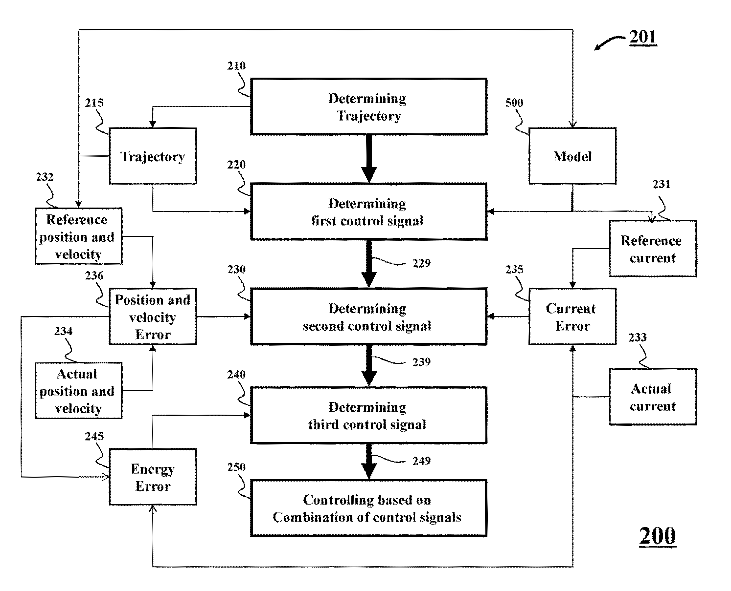
[0024]FIG. 2 shows a block diagram of a method 200 for controlling an operation of an actuator according to some embodiments of an invention. The actuator can be suitable for usage in a break system of an elevator. However, the embodiments can control a moving element (ME) of various types of the actuators, e.g., electromagnetic actuators. Embodiments of the invention can be implemented using a processor 201.

[0025]The method 200 determines 210 a trajectory 215 of a position of the ME as a function of time and determines 220 a first control signal 229 based on a model of the actuator, e.g., a model 500, and the trajectory 215. The first control signal is determined to change a position of the ME according to the trajectory.

[0026]A second control signal 239 is determined 230 to compensate for a first component of an error of the operation due to an uncertainty of a model of the actuator system. For example, the second signal can be determined based on a position and velocity error 236...


PUM


Abstract

A method controls an operation of a system. The system is operated by a controller. The controller is model-based controller determined according to a model of the system. The method updates the model, during the operation, based on an extremum seeking, and updates the controller based on the updated model.

Description

FIELD OF THE INVENTION[0001]This invention relates generally to controlling an operation of a system based on a model of the system, and more particularly to updating the model of the system based on an extremum seeking.BACKGROUND OF THE INVENTION[0002]FIG. 1A shows a schematic representation of an exemplar actuator. The actuator of FIG. 1A is an electromagnetic actuator. The actuator includes a casing 103, two coils 104, two springs 105, rubber cushions 102, a moving element (ME) 101, and a fixed element 100.[0003]Usually, the ME 101 comes in contact with the fixed mechanical element 100 when the actuator is not actuated. To move the ME 101 towards the casing 103, the actuator system is actuated by injecting a current in the coil 104. When the current is cancelled, the ME is pushed against the fixed element 100 by a spring force generated by the springs 102 positioned between the actuator casing 103 and the ME 101. To dampen the contact force, rubber cushions 102 are inserted betwe...

Claims


Application Information

Patent Timeline
IPC IPC(8): G05B13/04
CPCG05B17/02B66B1/32G05B13/042
Inventor BENOSMAN, MOUHACINE
Owner MITSUBISHI ELECTRIC RES LAB INC
Why Eureka
Try Eureka