Scheduling access requests for a multi-bank low-latency random read memory device

a random read and access request technology, applied in the field of storage systems, can solve the problem that conventional storage architectures may exhibit decreasing data access performan

Active Publication Date: 2013-11-14
NETWORK APPLIANCE INC
View PDF6 Cites 28 Cited by
  • Summary
  • Abstract
  • Description
  • Claims
  • Application Information

AI Technical Summary

Benefits of technology

[0009]Described herein are method and apparatus for scheduling access requests for a multi-bank low-latency random read memory (LLRRM) device for using the LLRRM device in a storage system. The LLRRM device may comprise a plurality of memory banks, each memory bank having an associated LLRRM address range, each memory bank being simultaneously and independently accessible for accessing data stored on the memory bank. A queuing layer residing in an operating system of the storage system may allocate a plurality of request-queuing data structures, each request-queuing data structure being assigned to a memory bank. The queuing layer may receive access requests for memory banks in the LLRRM device and store / queue each received access request in the request-queuing data structure assigned to the requested memory bank. The queuing layer may then send, to the LLRRM device for processing, an access request from each request-queuing data structure in successive order. As such, requests sent to the LLRRM device will comprise requests that will be applied to each memory bank in successive order as well, thereby reducing idle time of the banks and reducing access latencies of the LLRRM device.
[0010]For example, the queuing layer may be configured to recognize the specific configuration of memory banks in the LLRRM device and store / queue a received access request for a particular bank behind other access requests corresponding to the same bank so as not to block requests corresponding to unrelated banks. Further, the queuing layer may be configured to recognize the idle / not-idle state of the LLRRM memory banks such that the queuing layer may dispatch to the LLRRM device access requests from any queue in a scheduled order, thereby reducing idle time of the banks and reducing access latencies of the LLRRM device.
[0011]For example, the plurality of memory banks comprises first, second, and third memory banks, the first memory bank having an allocated first request-queuing data structure (“queue”), the second memory bank having an allocated second queue, and the third memory bank having an allocated third queue. The queuing layer may then send, to the LLRRM device, requests from each queue in a scheduled order, whereby the scheduled order is determined at least partially based on the idle / not-idle state of the LLRRM memory bank corresponding to the queue. For example, the queuing layer may combine idle / not-idle state with a circular polling technique in order to dispatch an awaiting and ready access request in a queue to a corresponding memory bank, and proceed to poll the next queue for an awaiting and ready access request, and dispatching that access request to the corresponding memory bank and so on continually. In this way, the queuing layer may continually dispatch to the LLRRM device a next awaiting access request in a queue to the corresponding and ready memory bank in the LLRRM device, thereby reducing idle time of the banks and reducing access latencies of the LLRRM device.
[0013]In some embodiments, each request-queuing data structure stores read and write requests for an assigned bank. In these embodiments, only the requested LLRRM address of the received access request and the LLRRM address range field is used to determine the queue identifier of the request-queuing data structure that is to store / queue the received access request. In other embodiments, each request-queuing data structure stores only read requests or only write requests for an assigned bank(s). In these embodiments, the requested LLRRM address of the received access request and the LLRRM address range field, as well as the request type identifier field is used to determine the queue identifier of the request-queuing data structure that is to store / queue the received access request. By providing separate request-queuing data structures for write requests, pending read requests can be processed by the LLRRM device with high priority, and without waiting behind higher-latency write requests.

Problems solved by technology

As the number of banks and the storage capacity of the LLRRM device increases, however, conventional storage architectures may exhibit decreasing data access performance (e.g., as measured by bandwidth over capacity).

Method used


Image

  • Scheduling access requests for a multi-bank low-latency random read memory device
  • Scheduling access requests for a multi-bank low-latency random read memory device
  • Scheduling access requests for a multi-bank low-latency random read memory device

Examples


Embodiment Construction

[0029]The disclosure of United States Patent Application entitled “SCHEDULING ACCESS REQUESTS FOR A MULTI-BANK LOW-LATENCY RANDOM READ MEMORY DEVICE,” having Ser. No. 12 / 430,776, filed on Apr. 27, 2009, is expressly incorporated herein by reference.

[0030]In the following description, numerous details are set forth for purpose of explanation. However, one of ordinary skill in the art will realize that the embodiments described herein may be practiced without the use of these specific details. In other instances, well-known structures and devices are shown in block diagram form in order not to obscure the description with unnecessary detail.

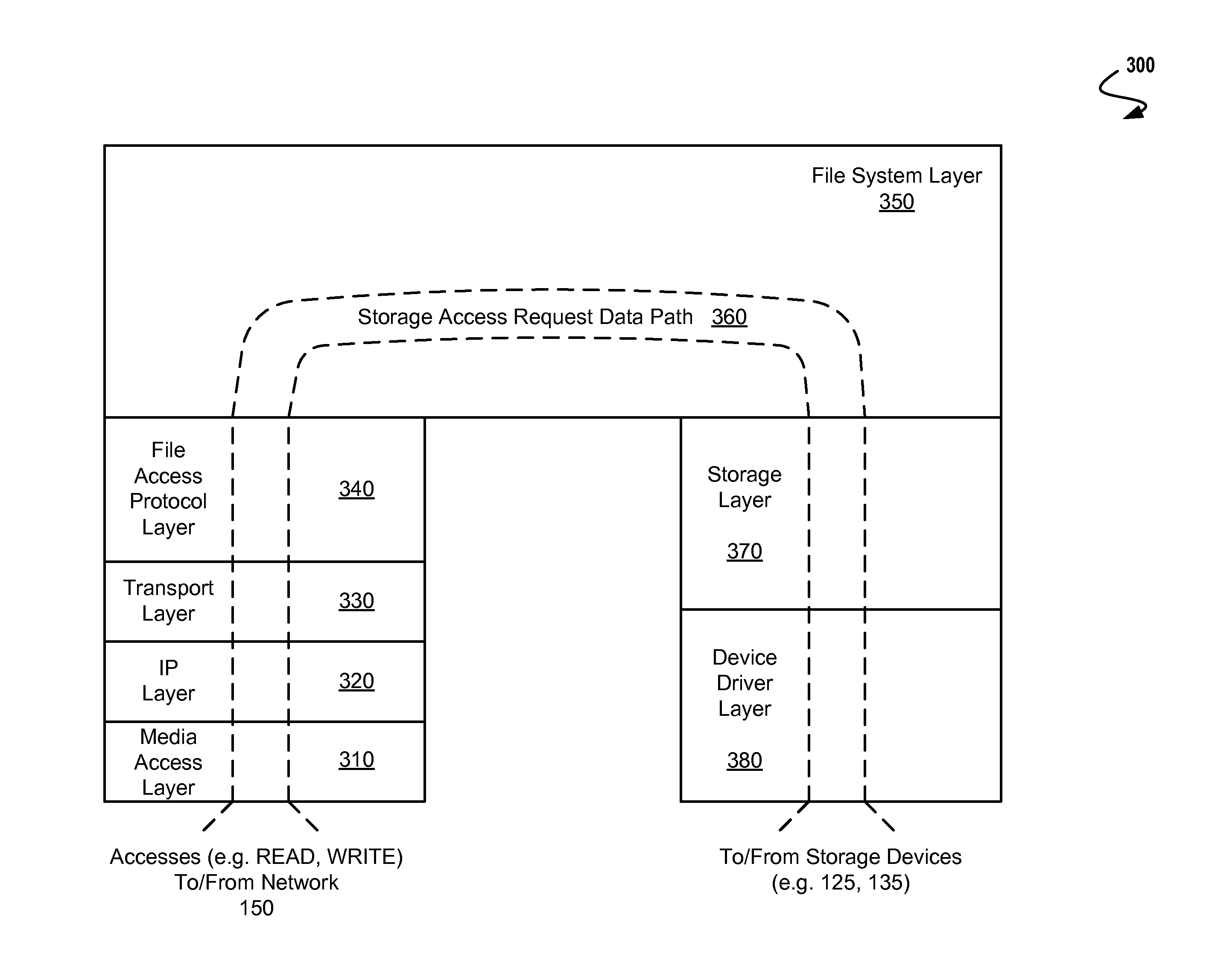
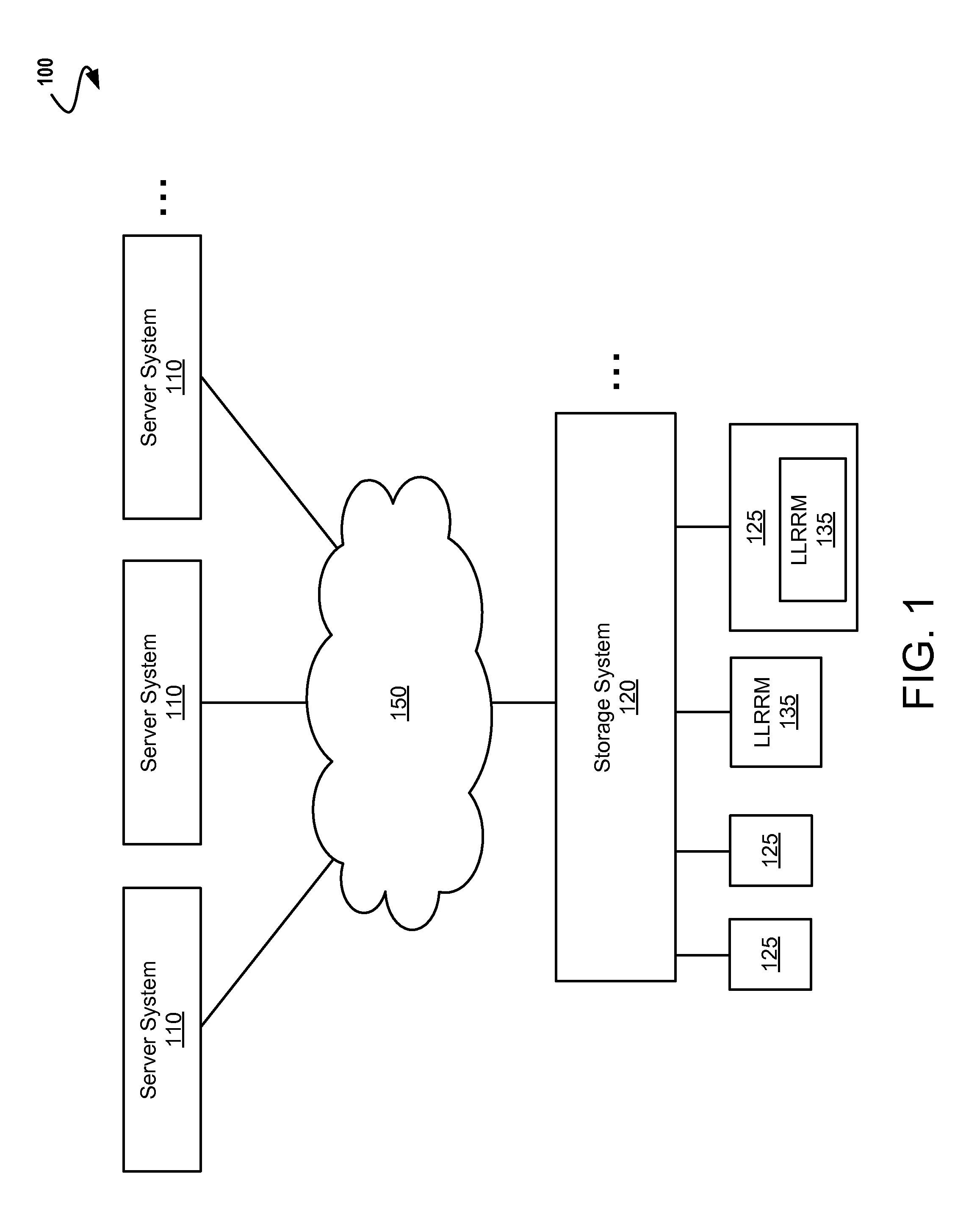
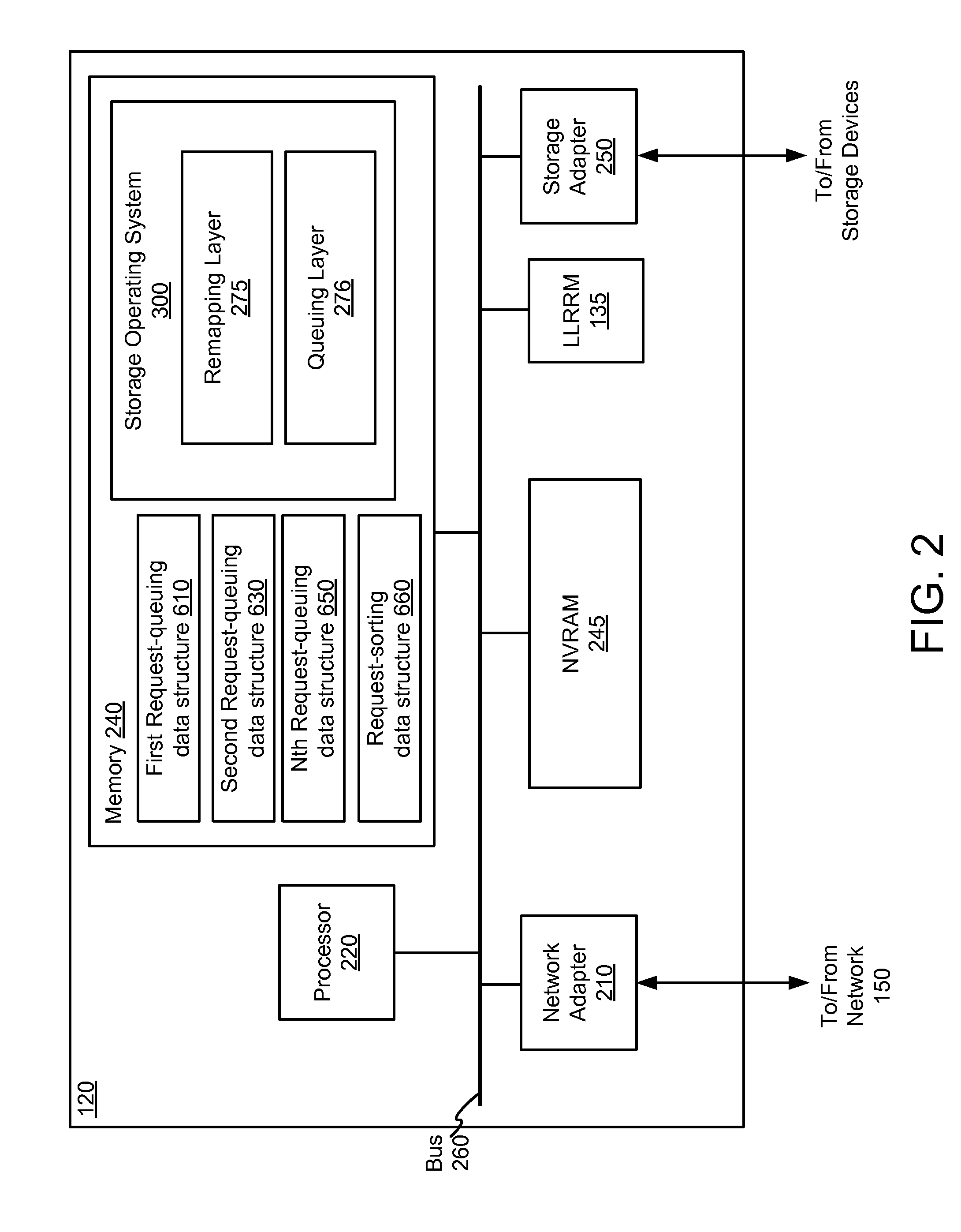
[0031]The description that follows is divided into four sections: Section I describes a storage system environment in which some embodiments operate. Section II describes a storage operating system engine having a queuing layer for using a low-latency random read memory device (LLRRM) as a storage device in a storage system. Section III describes a...


PUM


Abstract

Described herein are method and apparatus for scheduling access requests for a multi-bank low-latency random read memory (LLRRM) device within a storage system. The LLRRM device comprising a plurality of memory banks, each bank being simultaneously and independently accessible. A queuing layer residing in storage system may allocate a plurality of request-queuing data structures (“queues”), each queue being assigned to a memory bank. The queuing layer may receive access requests for memory banks in the LLRRM device and store each received access request in the queue assigned to the requested memory bank. The queuing layer may then send, to the LLRRM device for processing, an access request from each request-queuing data structure in successive order. As such, requests sent to the LLRRM device will comprise requests that will be applied to each memory bank in successive order as well, thereby reducing access latencies of the LLRRM device.

Description

RELATED APPLICATIONS[0001]This patent application claims benefit to and is a continuation of the United States Patent Application entitled “SCHEDULING ACCESS REQUESTS FOR A MULTI-BANK LOW-LATENCY RANDOM READ MEMORY DEVICE,” having Ser. No. 12 / 430,776, filed on Apr. 27, 2009, which is expressly incorporated herein by reference.FIELD OF THE INVENTION[0002]The present invention relates to storage systems, and particularly, to scheduling access requests for a multi-bank low-latency random read memory device.BACKGROUND OF THE INVENTION[0003]A storage system is a processing system adapted to store and retrieve data on storage devices (such as disks). The storage system includes a storage operating system that implements a file system to logically organize the data as a hierarchical structure of directories and files on the storage devices. Each file may be implemented as a set of blocks configured to store data (such as text), whereas each directory may be implemented as a specially-forma...

Claims


Application Information

Patent Timeline
Patent Type & Authority Applications(United States)
IPC IPC(8): G06F3/06
CPCG06F3/0631G06F3/0689G06F3/0613G06F13/1684G06F12/06G06F13/00G06F13/28
Inventor TOTOLOS, JR., GEORGENGUYEN, NHIEM T.
Owner NETWORK APPLIANCE INC
Why Eureka
Try Eureka