Heat dissipation systems with hygroscopic working fluid

a working fluid and heat dissipation system technology, applied in the direction of heating types, lighting and heating apparatus, domestic cooling apparatus, etc., can solve the problems of poor air cooling process efficiency, few opportunities for cooling in the future, inferior cooling of air, etc., and achieve the effect of reducing water consumption

Inactive Publication Date: 2013-11-21
ENERGY & ENVIRONMENTAL RES CENT FOUNDATIO
View PDF21 Cites 43 Cited by
  • Summary
  • Abstract
  • Description
  • Claims
  • Application Information

AI Technical Summary

Benefits of technology

[0014]A heat dissipation system apparatus and method of operation using hygroscopic working fluid for use in a wide variety of environments for absorbed water in the hygroscopic working fluid to be released to minimize water consumption in the heat dissipation system apparatus for effective cooling in environments having little available water for use in cooling systems.

Problems solved by technology

However, few of these opportunities for cooling are expected to be available in the future because competition for water sources and recognition of the impact of various uses of water sources on the environment are increasing.
These technologies are used routinely in industry, but each one has distinct drawbacks.
In the sensible cooling case, air is an inferior coolant compared to liquids, and the resulting efficiency of air-cooled processes can be poor.
In addition to larger surface area requirements, air-cooled heat exchangers approach the cooling limitation of the ambient dry-bulb temperature of the air used for cooling, which can vary 30° to 40° F. over the course of a day and can hinder cooling capacity during the hottest hours of the day.
Choosing the lowest initial cost option can have negative energy consumption implications for the life of the system.
The key drawback or problem associated with this cooling approach is the associated water consumption used in cooling, which in many areas is a limiting resource.
Obtaining sufficient water rights for wet cooling system operation delays plant permitting, limits site selection, and creates a highly visible vulnerability for opponents of new development.
As the ambient air's moisture content decreases, the required recirculation flow grows to become a larger and larger proportion of the total flow such that no significant cooling of the condenser is taking place, thereby reducing the ability of the heat dissipation system to cool, in the extreme, to near zero or no significant cooling.
Ultimately, once the hygroscopic desiccant is no longer a stable liquid under the prevalent environmental conditions, no amount of recirculation flow can prevent crystallization of the unheated hygroscopic desiccant solution.
Otherwise, the hygroscopic desiccant may completely dry out and precipitate from solution.
This limitation would exclude operation and use of the heat dissipation system described in U.S. Pat. No. 3,666,246 in regions of the world that experience significantly drier weather patterns, less humid air, and are arguably in need of improvements to dry cooling technology.
Additionally, while the heat dissipation system described in U.S. Pat. No. 3,666,246 discloses that the system may alternatively be operated to absorb atmospheric moisture and subsequently evaporate it, the disclosed heat dissipation system design circumvents most of this mode of operation of the heat dissipation system.
These systems can use less water compared to complete latent cooling, but any increased system performance is directly related to the amount of water-based augmentation, so these systems do not solve the underlying issue of water consumption.
Sensible cooling with air is costly because of the vast heat exchange surface area required and because its heat-transfer performance is handicapped during the hottest ambient temperatures.
Latent or evaporative cooling has preferred cooling performance, but it consumes large quantities of water which is a limited resource in some locations.

Method used


Image

  • Heat dissipation systems with hygroscopic working fluid
  • Heat dissipation systems with hygroscopic working fluid
  • Heat dissipation systems with hygroscopic working fluid

Examples


Embodiment Construction

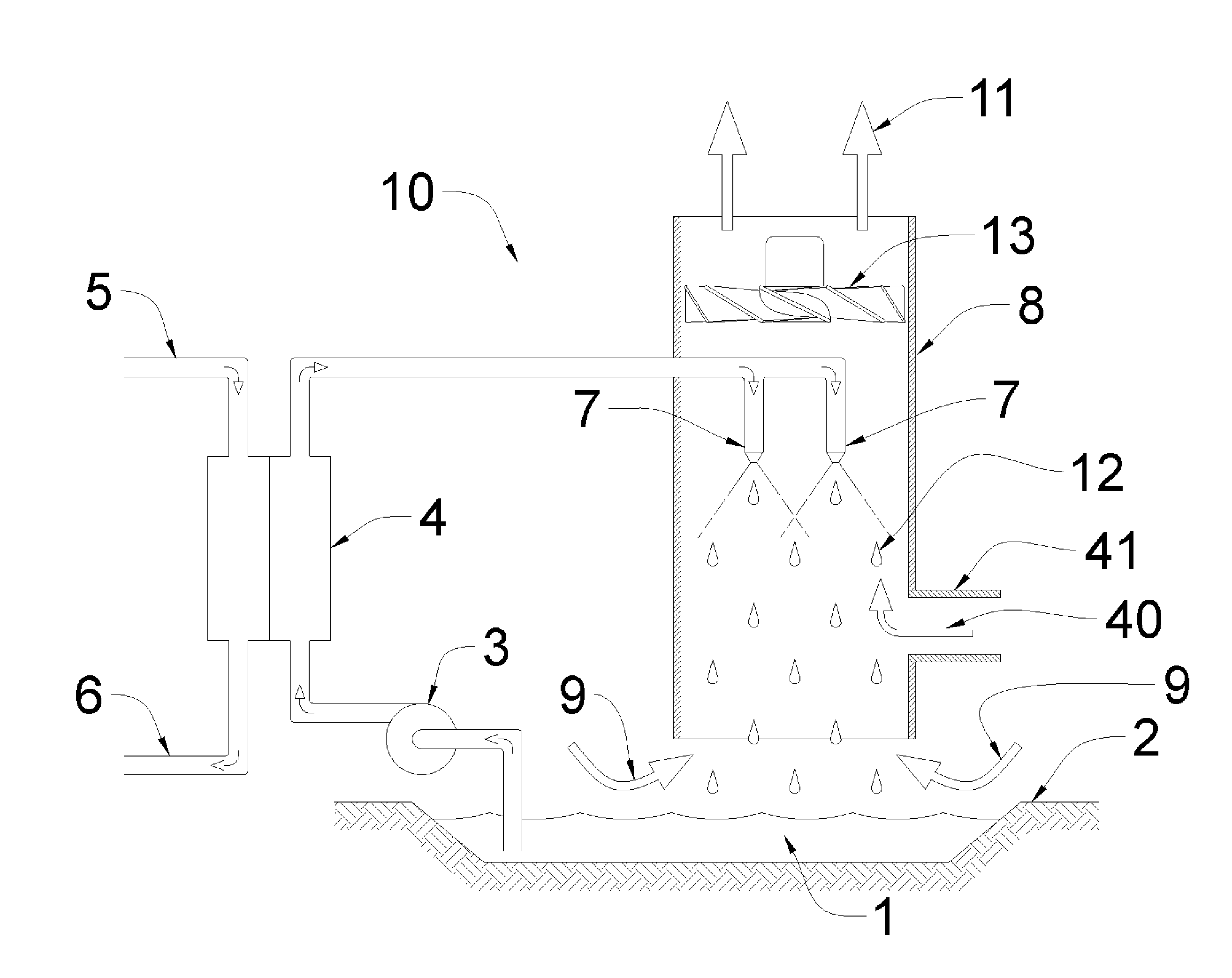
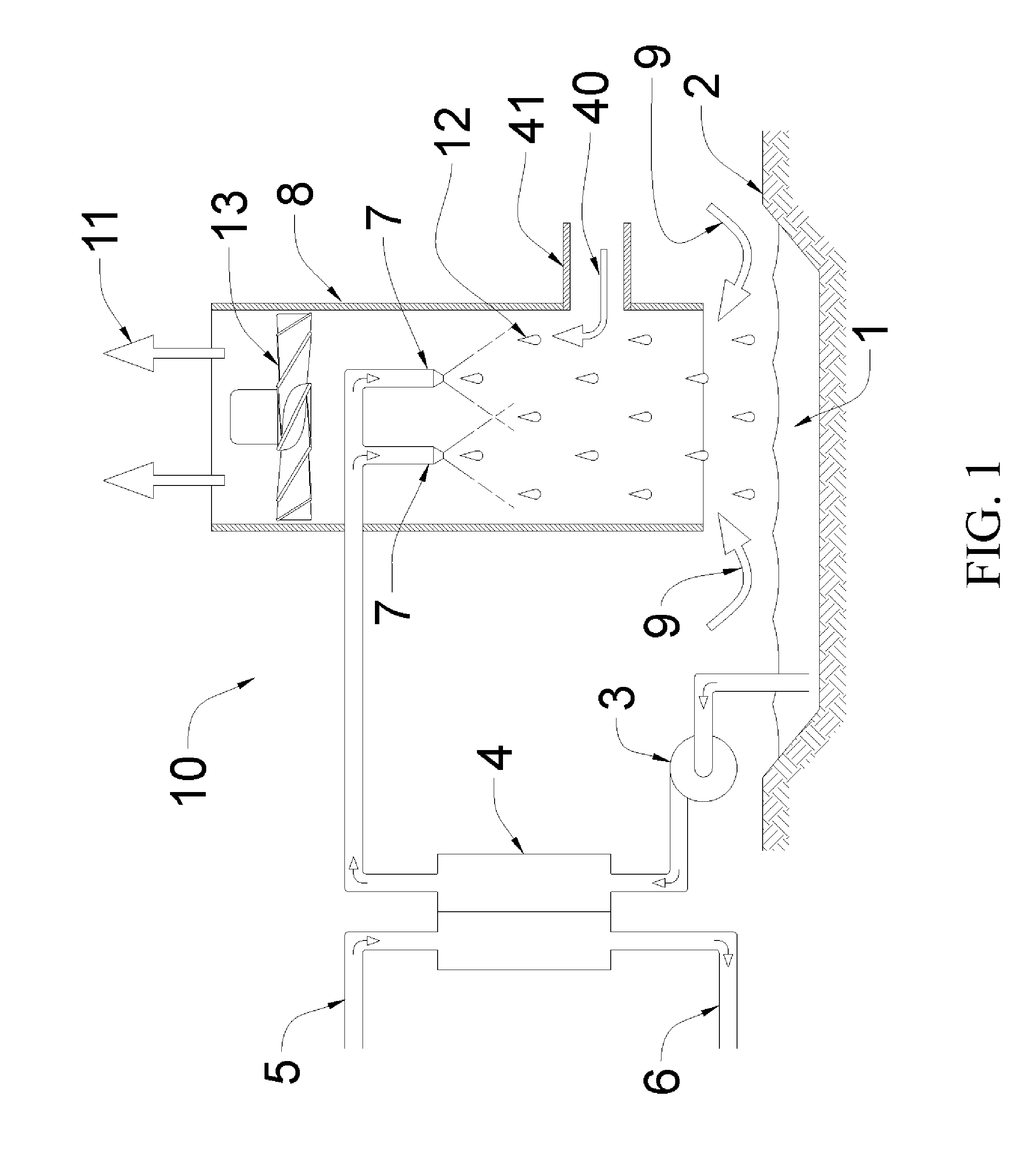
[0029]The heat dissipation systems described herein are an improvement to the state of the art in desiccant-based (hygroscopic) fluid cooling systems by incorporating means to regulate the amount of sensible heat transfer, e.g., heat exchanged having as its sole effect a change of temperature versus latent heat transfer, e.g., heat exchanged without change of temperature, taking place in heat dissipation system so that the desiccant-based hygroscopic fluid remains stable (hygroscopic desiccant in solution) to prevent crystallization of the desiccant from the desiccant-based hygroscopic fluid. In simple form, the heat dissipation system comprises at least one hygroscopic desiccant-to-air direct-contact heat exchanger for heat exchange having combined sensible and latent heat transfer, at least one sensible heat exchanger for heat exchange with a change of temperature of the heat exchange fluid used, and at least one desiccant (hygroscopic) fluid for use as the heat exchange fluid in ...


PUM


Abstract

A heat dissipation system apparatus and method of operation using hygroscopic working fluid for use in a wide variety of environments for absorbed water in the hygroscopic working fluid to be released to minimize water consumption in the heat dissipation system apparatus for effective cooling in environments having little available water for use in cooling systems. The system comprises a low-volatility, hygroscopic working fluid to reject thermal energy directly to ambient air. The low-volatility and hygroscopic nature of the working fluid prevents complete evaporation of the fluid and a net consumption of water for cooling, and direct-contact heat exchange allows for the creation of large interfacial surface areas for effective heat transfer. Specific methods of operation prevent the crystallization of the desiccant from the hygrosopic working fluid under various environmental conditions.

Description

CROSS-REFERENCE TO RELATED APPLICATIONS[0001]This application is a continuation-in-part of and claims the benefit of priority under 35 U.S.C. §120 to U.S. Utility application Ser. No. 13 / 040,379 entitled “HEAT DISSIPATION SYSTEM WITH HYGROSCOPIC WORKING FLUID,” filed Mar. 4, 2011, which claims the benefit under 35 U.S.C. §119(e) of U.S. Provisional Patent Application Ser. No. 61 / 345,864 filed May 18, 2010, the disclosures of which are incorporated herein in their entirety by reference.STATEMENT REGARDING FEDERALLY SPONSORED RESEARCH OR DEVELOPMENT[0002]This invention was made with government support under Cooperative Agreement No. DE-FC26-08NT43291 entitled “EERC-DOE Joint Program on Research and Development for Fossil Energy-Related Resources,” awarded by the U.S. Department of Energy (DOE). The government has certain rights in the invention.FIELD OF THE INVENTION[0003]This invention relates to the dissipation of degraded thermal energy to ambient air.BACKGROUND OF THE INVENTION[00...

Claims


Application Information

Patent Timeline
Patent Type & Authority Applications(United States)
IPC IPC(8): F25D17/06
CPCF25D17/06F24F3/1417F28C1/14F28B9/06
Inventor MARTIN, CHRISTOPHER L.
Owner ENERGY & ENVIRONMENTAL RES CENT FOUNDATIO
Why Eureka
Try Eureka