Dehydrator

A dehydrator and dehydration technology, which is applied in the fields of filtration and separation, fixed filter element filters, chemical instruments and methods, etc., can solve the problems of low dehydration efficiency, change of discharge pressure, decrease of operation rate, etc., and achieve simple structure and operation method. and simplicity, increase the pushing capacity and extrusion, and improve the effect of the operation rate

Inactive Publication Date: 2014-08-13
GREEN TEC
View PDF8 Cites 15 Cited by
  • Summary
  • Abstract
  • Description
  • Claims
  • Application Information

AI Technical Summary

Problems solved by technology

[0011] In the screw type dehydrator described in the prior art, it is necessary to uniformly pressurize the ring-shaped pressurizing plate by rotating a plurality of pressurizing shafts supporting the pressurizing plate. Therefore, it is difficult to uniformly adjust and Maintain the discharge pressure of the entire discharge port
As described above, the adjustment of the pressurizing force by rotating the plurality of shafts is cumbersome, and it is difficult to respond quickly when the discharge pressure needs to be changed.
[0012] In addition, the dehydrated matter falls through the discharge port on the lower side formed at the lower part of the discharge cylinder, so there are difficulties in that it is necessary to install a conveyor belt at the lower part of the dehydrator or to collect and transport the dehydrated matter dropped on the bottom surface by manpower.
[0013] In addition, in the case of conventional screw dehydrators, sliding occurs between the object to be dehydrated and the screw, so the extrusion and pushing capabilities of the screw are insufficient, the dehydration efficiency is low, and the screen is often clogged and washed with water, resulting in waste water There is a large amount of generation, the operation rate is also reduced, and the pressure energy for discharging the dehydrated material cannot be used for the transfer, molding, crushing, etc. of the dehydrated material, and it is wasted. Therefore, it is necessary to improve this.
[0014] On the other hand, the conventional screw dehydrator has a structure in which the pressure energy for discharging the dehydrated product cannot be used for the transfer and molding of the dehydrated product, especially, it cannot be used for additional dehydration to improve the dehydration efficiency, and is wasted. , so this needs to be improved

Method used


Image

  • Dehydrator
  • Dehydrator
  • Dehydrator

Examples


Embodiment Construction

[0048] Hereinafter, the dehydrator according to the present invention will be described in detail with reference to the accompanying drawings.

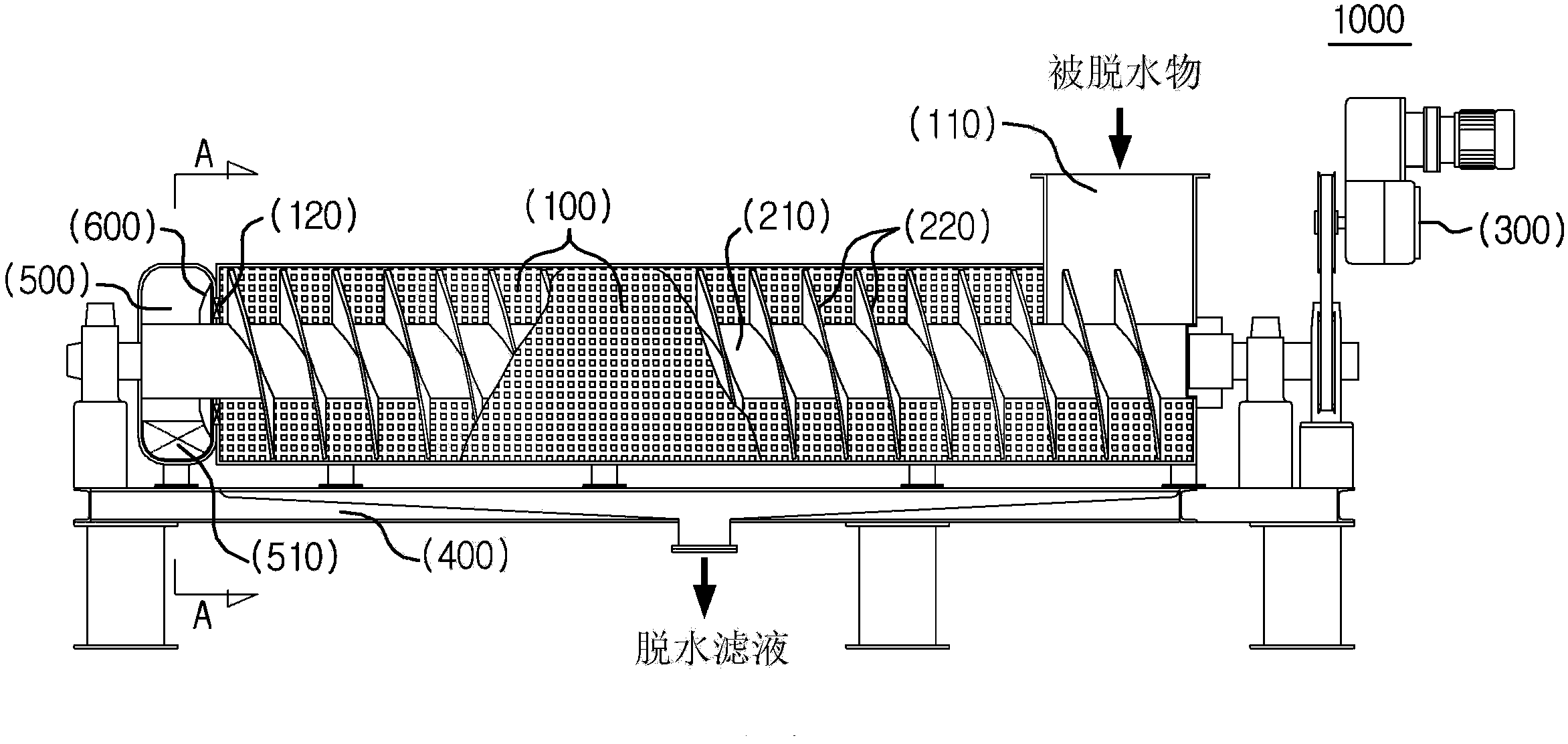
[0049] figure 1 is a front sectional view of a dehydrator according to the present invention.

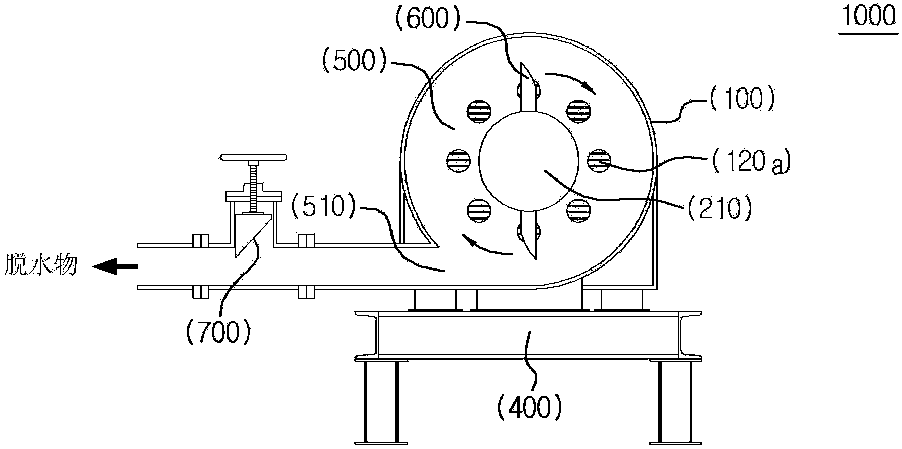
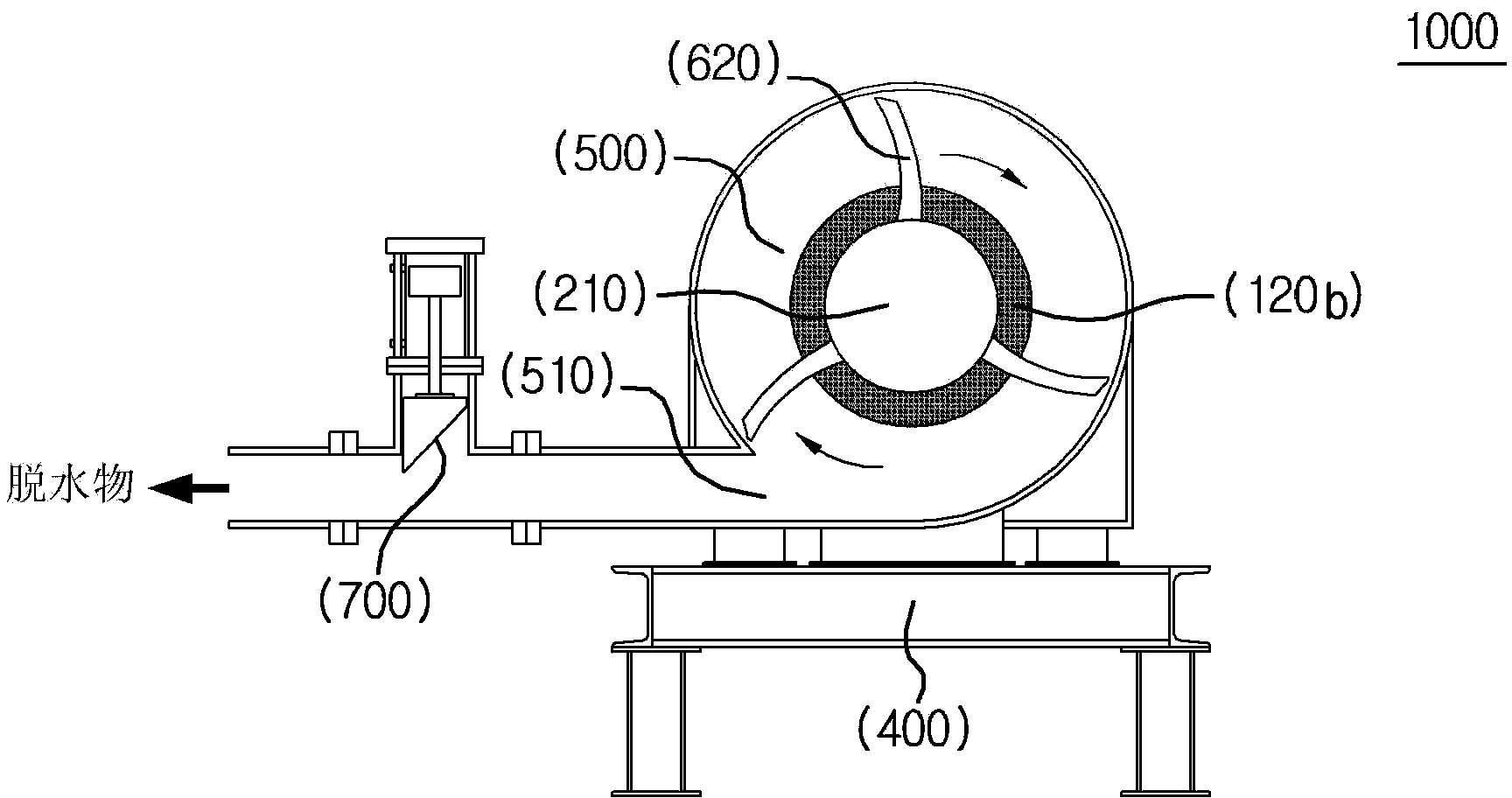
[0050] The dehydrator according to the basic concept of the present invention includes: a cylindrical screen 100 formed with a plurality of fine holes; a screw consisting of a rotating shaft 210 and a helical rotating blade 220; a driving part 300 which makes the The screw rotates; the input port 110 is arranged on one side of the sieve, and the dehydrated matter is put into the inside of the sieve; the discharge port 120 is arranged on the other side of the sieve, and the dehydrated matter is discharged to the outside of the sieve The pressurization chamber 500, which communicates with the discharge port, stores the discharged dehydrated matter inside and pressurizes; the discharge port 510, which is formed in the pressurized chamber, dis...


PUM


Abstract

The present invention relates to a dehydrator dehydrating various dehydrated objects containing water and solid bodies. By means of a rotating screw in a driving portion, the dehydrator performs driving inside a cylindrical sieve equipped with an inlet and a discharge outlet such that the dehydrated objects are dehydrated by extrusion. The dehydrator may function various advantages that the discharge outlet is equipped with pressurization chamber with a discharge opening and a pressure regulating unit communicated with the discharge opening, dehydrating pressure can be regulated by simple operation, in another aspect, a push auxiliary unit is arranged on the screw so as to enhance a pressing and pushing capability, a rotary impeller is provided so as to prevent the jamming of the discharge outlet and increase discharging pressure, and the dehydrator is used as a pressure feed pump for pressing and feeding the dehydrated objects .

Description

[0001] The present invention claims the priority of Korean Patent Application No. 10-2013-0013869 (filed on February 2, 2013) and 10-2013-0028604 (filed on March 18, 2013), which are cited here Its entire contents are provided by reference. technical field [0002] The present invention relates to a dehydrator that squeezes and dehydrates dehydrated materials such as raw materials containing moisture, products in process, food, food waste, and sludge generated in sewage treatment plants, and separates them into dehydrated products with low moisture content and dehydrated filtrate. Specifically, it relates to a screw type dehydrator that squeezes and dehydrates a material to be dehydrated by a screw rotating inside a cylindrical fine sieve. Background technique [0003] Dehydration machines include centrifugal dehydration machines, belt presses, filter presses, etc. [0004] As far as the centrifugal dehydrator is concerned, due to its compact structure, small footprint, and...

Claims


Application Information

Patent Timeline
Patent Type & Authority Applications(China)
IPC IPC(8): B01D29/05
Inventor 韩相培
Owner GREEN TEC
Why Eureka
Try Eureka