
Asymmetric Field Ion Mobility in a Linear Geometry Ion Trap

a linear geometry and ion trap technology, applied in the field of mass spectrometry, can solve the problems of ion diffusion being lost, ion not being transmitted, etc., and achieving the effect of low duty cycle for transmission of analytes, ion diffusion becoming a significant loss mechanism, and ion diffusion becoming a loss mechanism

Active Publication Date: 2013-11-21
MICROMASS UK LTD
View PDF4 Cites 24 Cited by
  • Summary
  • Abstract
  • Description
  • Claims
  • Application Information

AI Technical Summary

Benefits of technology

The invention is about a new method and system for separating ions using a linear ion trap or differential ion mobility separator. The main advantage of this invention is that it can operate at a lower pressure than conventional systems, which reduces the likelihood of ions being lost during scanning. Additionally, the use of high voltage RF generators is avoided, which makes the system more efficient.

Problems solved by technology

At atmospheric pressure the rate of ion diffusion is lower than at reduced pressure and so as the gas pressure is reduced, ion diffusion becomes a significant loss mechanism.
Ions which have entered the device, but which are not being transmitted, will be lost.
This results in very low duty cycle for transmission of analytes having differing ion mobility characteristics during an analytical scan and hence low overall sensitivity.

Method used


Image

  • Asymmetric Field Ion Mobility in a Linear Geometry Ion Trap
  • Asymmetric Field Ion Mobility in a Linear Geometry Ion Trap
  • Asymmetric Field Ion Mobility in a Linear Geometry Ion Trap

Examples


Embodiment Construction

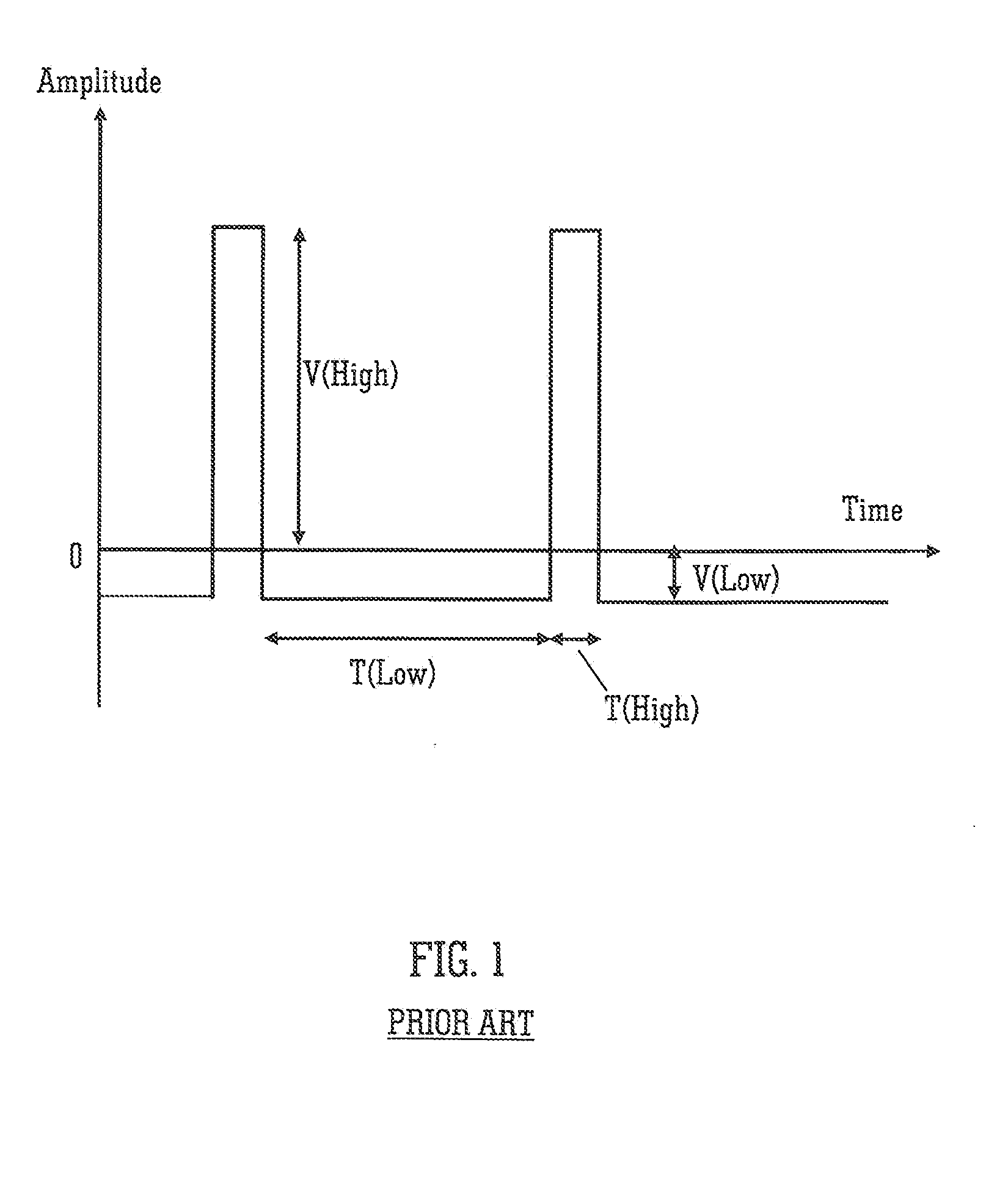
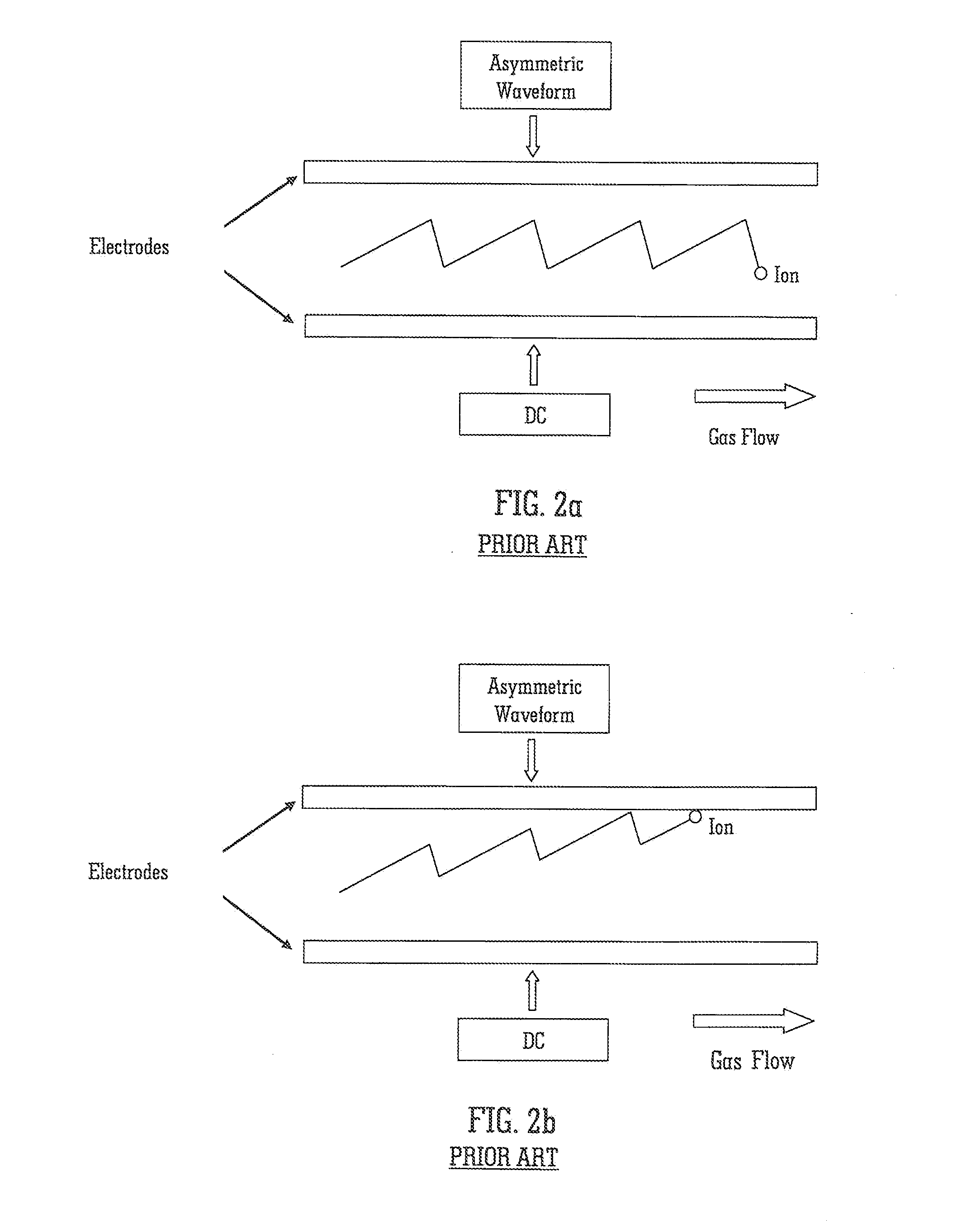
[0093]FIG. 1 shows a known asymmetric potential difference which may be applied between the plates of a known ion mobility separator in order to separate ions according to their differential ion mobility. The product of voltagetime is arranged to be the same for the low and high field sections of the wave. Consequently, if the low and high field mobility of an ion species are the same then the average trajectory of an ion will be parallel to the plates and the ion will be transmitted through the device as shown in FIG. 2A. However, if the low and high field mobilities differ, then the ion will drift towards one or other of the plates and be lost to the system as shown in FIG. 2B. Through application of a DC voltage to one plate it is possible to compensate for any mobility-induced drift and to allow transmission of ions having a desired differential ion mobility.

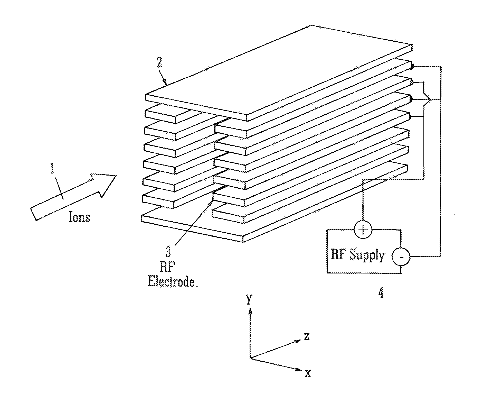
[0094]A preferred embodiment of the present invention will now be described with reference to FIG. 3. A stacked plate ion ...


PUM


Abstract

A linear ion trap is disclosed wherein an asymmetric voltage waveform is applied to electrodes forming the ion trap which causes ions to become radially separated according to their differential ion mobility. An axial potential barrier is arranged at the exit of the ion trap such that ions having a first differential ion mobility and a first radial displacement are retained axially within the ion trap but ions having a second differential ion mobility and a second radial displacement are ejected axially from the ion trap.

Description

CROSS-REFERENCE TO RELATED APPLICATION[0001]This application claims priority from and the benefit of U.S. Provisional Patent Application Ser. No. 61 / 421,387 filed 9 Dec. 2010 and United Kingdom Patent Application No. 1018184.0 filed on 27 Oct. 2010. The entire contents of this application are incorporated herein by reference.BACKGROUND TO THE INVENTION[0002]The present invention relates to the field of mass spectrometry and in particular to a differential ion mobility separator.[0003]The mobility K of an ion in a gas in the presence of an electric field E is essentially independent of the field under conditions where the energy gained from the field by the ion is negligible compared with thermal energies. This condition is met when E / N is low, wherein N is the neutral gas number density. However, as the electric field is increased or the neutral gas number density is decreased, then the mobility of an ion becomes dependent on the ratio of E / N:K(EN)=K0[1+α(EN)](1)wherein K0 is the lo...

Claims


Application Information

Patent Timeline
Patent Type & Authority Applications(United States)
IPC IPC(8): H01J49/04H01J49/00H01J49/36
CPCH01J49/04H01J49/36H01J49/0031H01J49/422G01N27/624H01J49/065G01N27/623H01J49/423
Inventor GILES, KEVINGREEN, MARTIN RAYMONDLANGRIDGE, DAVID J.
Owner MICROMASS UK LTD
Learn More