Capacitance change type power generation device

a power generation device and capacitive change technology, applied in piezoelectric/electrostrictive/magnetostrictive devices, electrostatic generators/motors, influence generators, etc., can solve the problem that document 2 is not always effective in providing sufficient power generation efficiency, and achieve high surface charge density, and high remanent polarization value

Inactive Publication Date: 2013-11-21
FUJIFILM CORP
View PDF1 Cites 18 Cited by
  • Summary
  • Abstract
  • Description
  • Claims
  • Application Information

AI Technical Summary

Benefits of technology

The invention is a power generation device that uses ferroelectric particles dispersed in a dielectric elastomer. These particles have crystal orientability, which allows them to be polarized in a way that maximizes their remanent polarization values. By aligning the polarization axes of the particles, the entire composite layer can have a high surface charge density. The elasticity of the elastomer also allows for changes in the distance between the electrodes, improving power generation capacity. Additionally, if the polarization axes of the particles with the highest permittivity are oriented parallel to the layer thickness direction, the permittivity can be reduced and higher power generation characteristics can be achieved.

Problems solved by technology

The patent text discusses the development of electroactive polymer artificial muscles (EPAMs) for converting mechanical energy into electric energy for power generation. The technical problem addressed in the text is the need for a reliable and efficient method to diagnose and prevent damage to the composite member used in the power generation system, which may occur during operation or transportation.

Method used


Image

  • Capacitance change type power generation device
  • Capacitance change type power generation device
  • Capacitance change type power generation device

Examples


Embodiment Construction

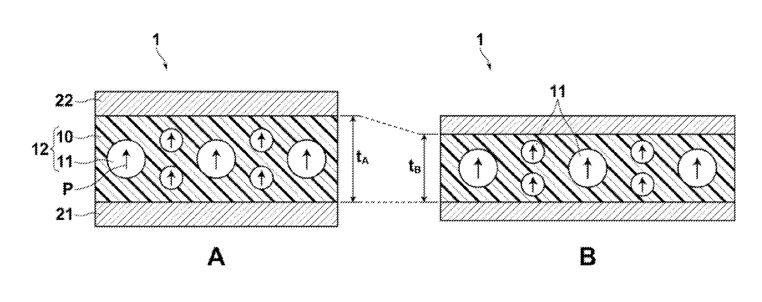
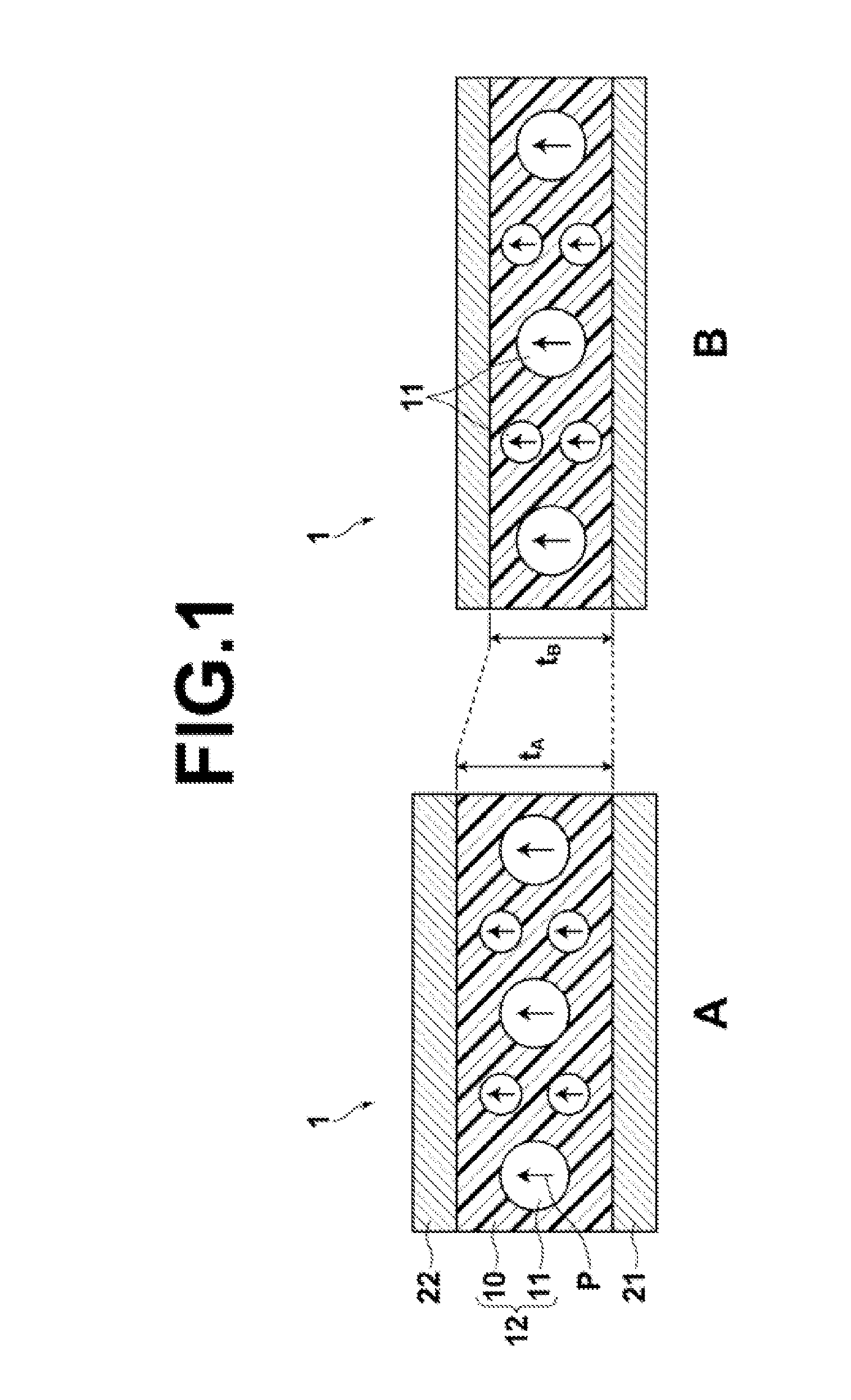
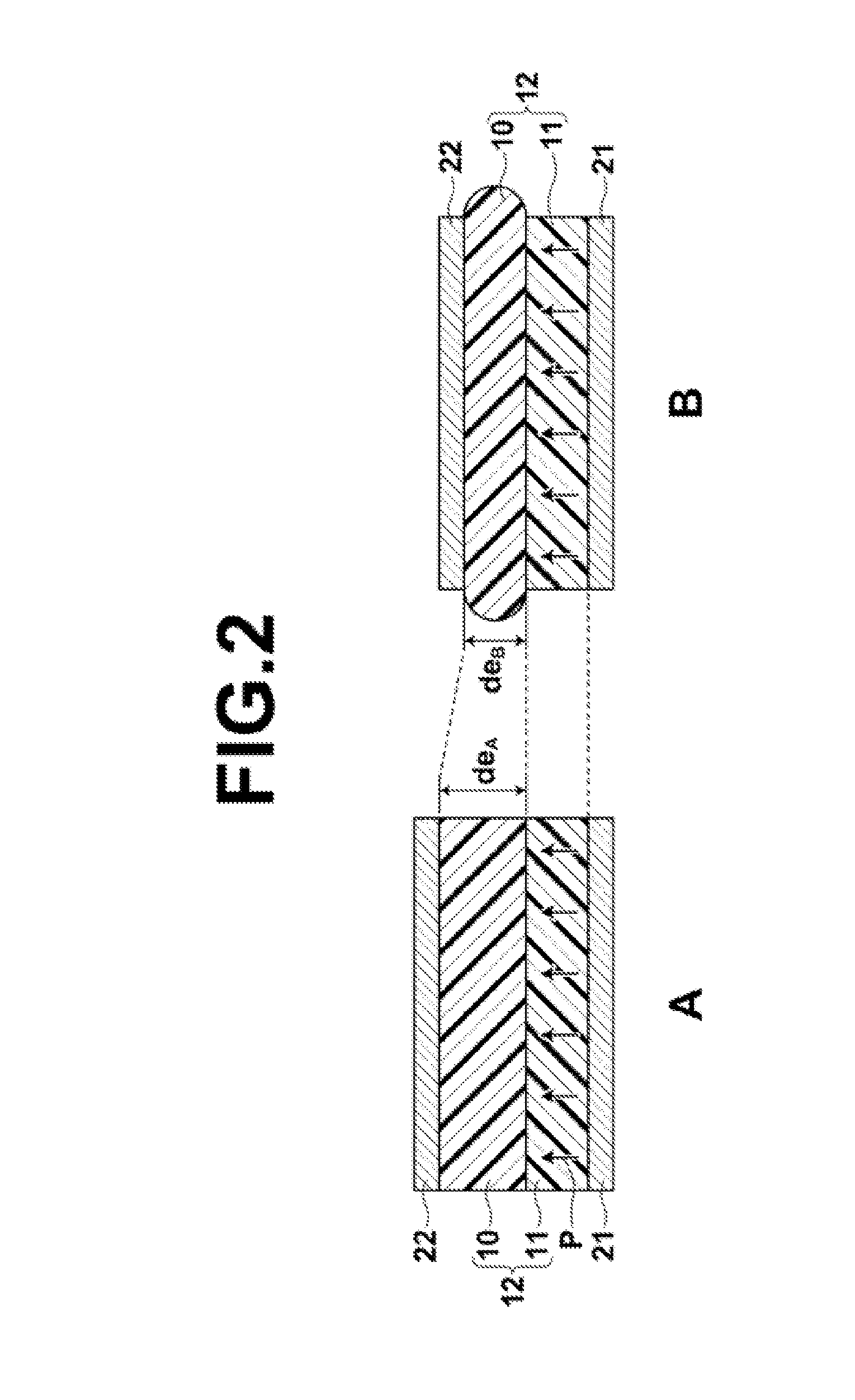
[0025]Hereinafter, a capacitance change type power generation device of the invention is described with reference to FIG. 1. FIG. 1 shows schematic sectional views of a power generation device 1 according to one embodiment of the invention, where an uncompressed state (state A) of the device is shown at A and a compressed state (state B) of the device is shown at B. For ease of visual understanding, the elements shown in the drawing are not to scale.

[0026]As shown in FIG. 1, the power generation device 1 includes a composite layer 12, which is formed by dispersing ferroelectric particles 11 in a dielectric elastomer 10, and a pair of electrodes 21 and 22, which are disposed on opposite sides of the composite layer 12 and are stretchable and compressible along with stretch and compression of the composite layer 12. In the power generation device 1, the ferroelectric particles 11 have crystal orientability and are orientationally dispersed in the dielectric elastomer 10 such that the ...


PUM


Abstract

A power generation device includes: a composite layer formed by a dielectric elastomer with ferroelectric particles dispersed therein; and a pair of electrodes disposed on opposite sides of the composite layer, the pair of electrodes being stretchable and compressible along with stretch and compression of the composite layer. The ferroelectric particles have crystal orientability and are orientationally dispersed in the dielectric elastomer, and are polarized in the layer thickness direction of the composite layer.

Description


Claims


Application Information

Patent Timeline
Owner FUJIFILM CORP
Why Eureka
Try Eureka