Antenna device and wireless communication apparatus

a wireless communication and antenna device technology, applied in the direction of antennas, antenna details, antenna couplings, etc., can solve the problems of difficult to reduce sar or electromagnetic wave interference in the hearing aid, and achieve the effect of reducing sar and electromagnetic influence on the hearing aid, weakening the electromagnetic field and reducing the sar and electromagnetic interferen

Inactive Publication Date: 2013-11-21
PANASONIC INTELLECTUAL PROPERTY MANAGEMENT CO LTD
View PDF0 Cites 4 Cited by
  • Summary
  • Abstract
  • Description
  • Claims
  • Application Information

AI Technical Summary

Benefits of technology

[0010]As described above, in the antenna device and the wireless communication apparatus according to the invention, as two ground antennas which are operated at the same frequency are used and the amplitude ratio and the phase difference of the antenna currents are adjusted so that the ground currents corresponding to the respective antenna currents cancel each other out, it is possible to weaken the electromagnetic field in the vicinity of the speaker, and to reduce the SAR and the electromagnetic influence on the hearing aid.

Problems solved by technology

Thus, in the mobile phone mounted with the monopole antenna, it is difficult to reduce the SAR or the electromagnetic wave interference in the hearing aid.

Method used


Image

  • Antenna device and wireless communication apparatus
  • Antenna device and wireless communication apparatus
  • Antenna device and wireless communication apparatus

Examples


first embodiment

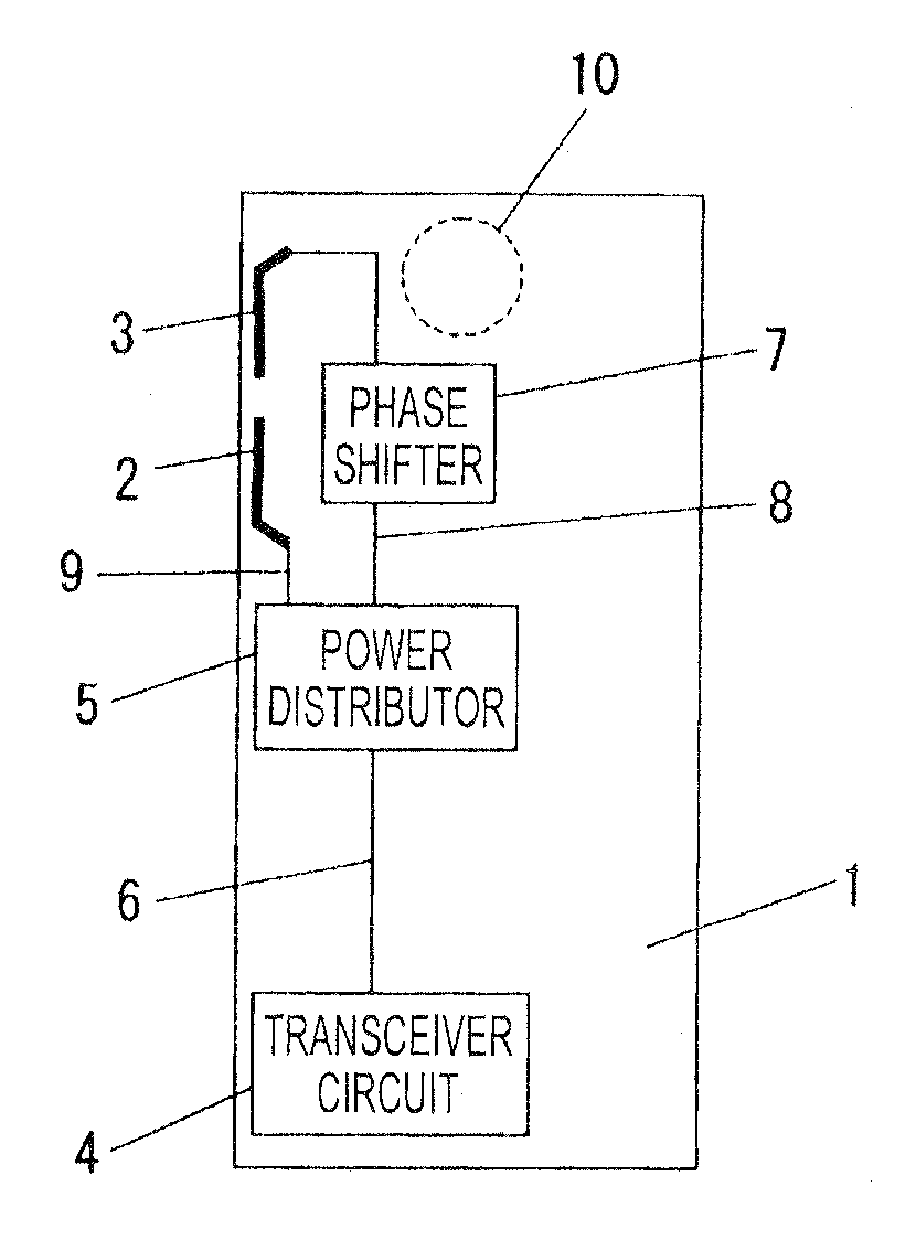
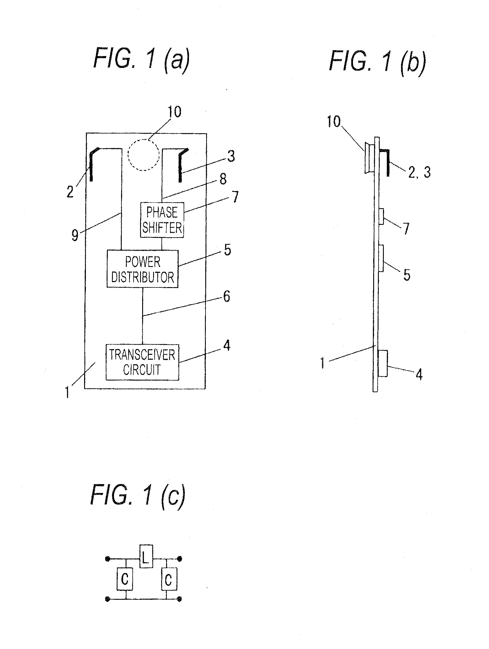
[0025]FIGS. 1(a) to (c) are diagrams illustrating an antenna device according to an embodiment of the invention. Reference numeral 1 in FIG. 1(a) represents a printed circuit board of a terminal main body, reference numeral 2 represents a first inverted L antenna that is provided in an upper portion of the printed circuit board 1, reference numeral 3 represents a second inverted L antenna that is provided in an upper portion of the printed circuit board 1, is operated at the same frequency as in the first inverted L antenna 2, and is laterally symmetrical in structure to the first inverted L antenna 2. The inverted L antenna has a structure in which a monopole antenna is bent in the middle thereof. The inverted L antenna 2 and the inverted L antenna 3 are installed at laterally symmetrical positions with reference to a central axis of the printed circuit board 1 having a laterally symmetrical shape. Reference numeral 4 represents a transceiver circuit provided in a lower portion of ...

second embodiment

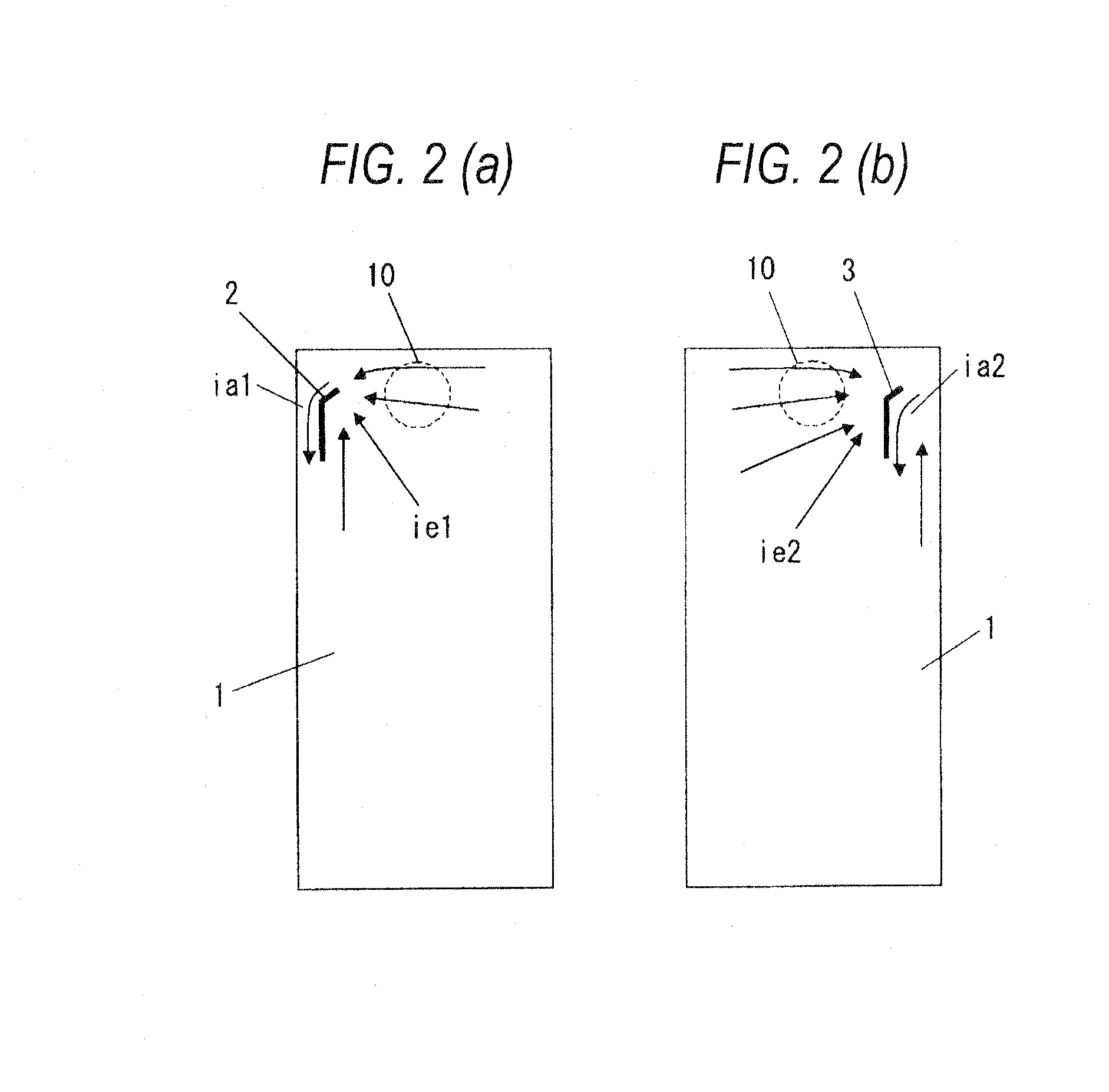
[0033]FIGS. 3(a) and 3(b) are diagrams illustrating an antenna device according to an embodiment of the invention. The same reference numerals are given to the same components as in FIGS. 1(a) to 1(c). In FIG. 3(a), reference numeral 1 represents a printed circuit board of a terminal main body, reference numeral 2 represents a first inverted L antenna provided on a left edge of the printed circuit board 1, reference numeral 3 represents a second inverted L antenna that is provided on the left edge of the printed circuit board thereof so that a direction where a radiation element extends from a power supply point is opposite the first inverted L antenna, and is operated at the same frequency as that of the first inverted L antenna 2. FIG. 3(b) is a side view of the antenna device shown in FIG. 3(a).

[0034]In the antenna device having such a configuration, a structure capable of reducing the electromagnetic field strength in the vicinity of the speaker 10 will be described referring to...

third embodiment

[0039]FIGS. 5(a), 5(b) and 5(c) are diagrams illustrating an antenna device according to an embodiment of the invention. The same reference numerals are given to the same components as in FIGS. 1(a) to 1(c).

[0040]Reference numeral 1 in FIG. 5(a) represents a printed circuit board of a terminal main body, reference numeral 11 represents a tabular F antenna provided in an upper portion of the printed circuit board 1 and is operated at two frequencies of a frequency fl and a frequency fh. Reference numeral 12 represents a ground point of the tabular inverted F antenna to the printed circuit board 1. Reference numeral 13 represents a power supply point of the tabular inverted F antenna 11. Reference numeral 14 represents an inverted L antenna that is provided on the printed circuit board 1 and is operated at the frequency fh. Reference numeral 15 represents a band-reject filter that rejects the passing of a high frequency signal of the frequency fl and passes a high frequency signal of ...


PUM


Abstract

The antenna device includes a first antenna 11 that includes a first ground terminal 12; a second antenna 18 that includes a second ground terminal 20; a ground conductor 28 to which the first antenna 11 is connected through the first ground terminal 12 and the second antenna 18 is connected through the second ground terminal 20; and a phase shifter 24 that controls a phase difference between a first current ie1 and a second current ie2. The phase shifter 24 controls the phase difference between the first current ie1 and the second current ie2 so that the first current ie1 and the second current ie2 have components to cancel each other.

Description

TECHNICAL FIELD[0001]The present invention relates to an antenna device and a wireless communication apparatus that are capable of reducing, in particular, a specific absorption rate (SAR), in a portable wireless terminal such as a mobile phone, in a head part of a human body, or the influence of an electromagnetic field on a hearing aid.BACKGROUND ART[0002]in the related art, a monopole antenna having a small size and a simple structure has been widely used as an antenna device of a mobile phone (refer to NPL 1). Hereinafter, an antenna device of a mobile phone that is mounted with the monopole antenna in the related art will be described referring to FIGS. 13(a) and 13(b).[0003]FIGS. 13(a) and 13(b) show an antenna structure of a monopole antenna mounted to a mobile phone and electric current distribution in operation. In FIG. 13(a), a ¼λ monopole antenna 102 is mounted to a printed circuit board 101 of a mobile phone main body through a power supply point 103. In FIGS. 13(a) and ...

Claims


Application Information

Patent Timeline
Patent Type & Authority Applications(United States)
IPC IPC(8): H01Q21/00
CPCH01Q21/0006H01Q1/245H01Q3/30H04B1/3838
Inventor BABA, JUNNEIASHIZUKA, TETSUYAKOMAKI, ICHIRO
Owner PANASONIC INTELLECTUAL PROPERTY MANAGEMENT CO LTD
Why Eureka
Try Eureka