Antenna device and wireless communication apparatus
a wireless communication and antenna device technology, applied in the direction of antennas, antenna details, antenna couplings, etc., can solve the problems of difficult to reduce sar or electromagnetic wave interference in the hearing aid, and achieve the effect of reducing sar and electromagnetic influence on the hearing aid, weakening the electromagnetic field and reducing the sar and electromagnetic interferen
- Summary
- Abstract
- Description
- Claims
- Application Information
AI Technical Summary
Benefits of technology
Problems solved by technology
Method used
Image
Examples
first embodiment
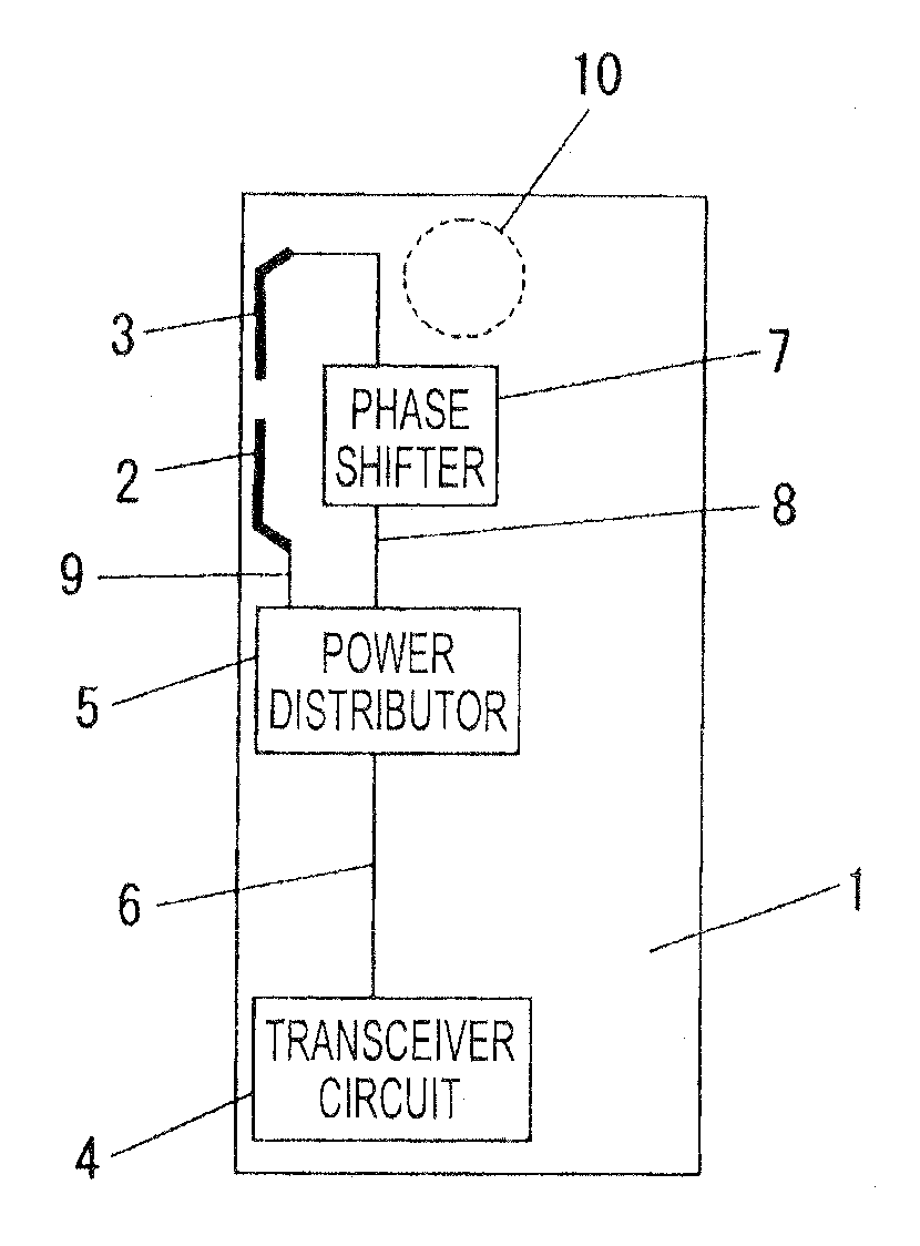
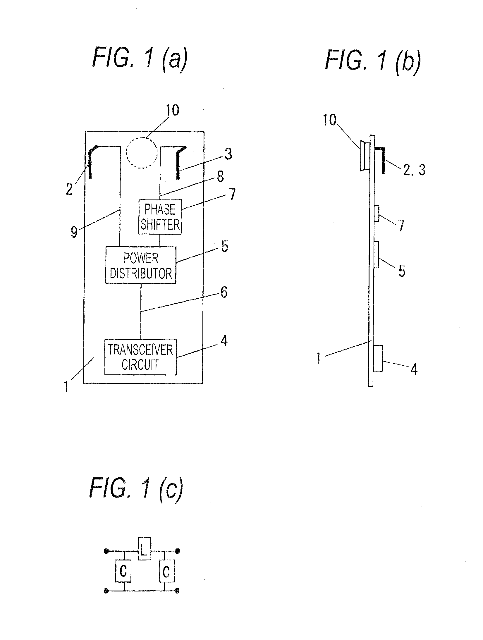
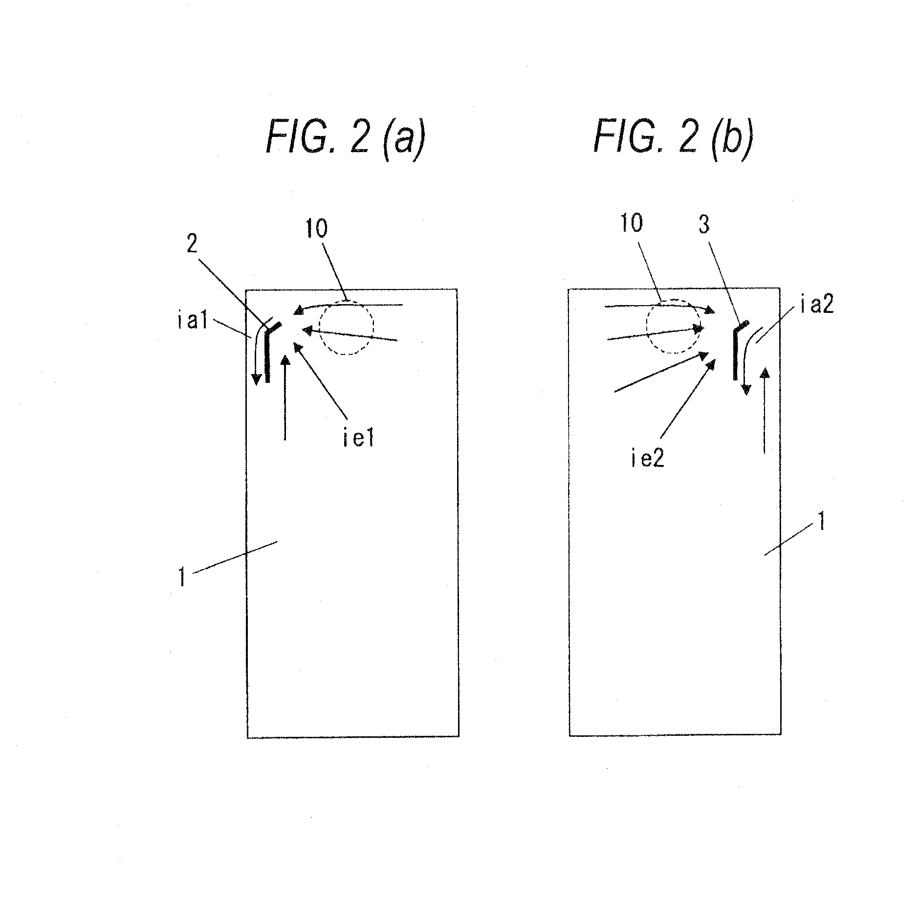
[0025]FIGS. 1(a) to (c) are diagrams illustrating an antenna device according to an embodiment of the invention. Reference numeral 1 in FIG. 1(a) represents a printed circuit board of a terminal main body, reference numeral 2 represents a first inverted L antenna that is provided in an upper portion of the printed circuit board 1, reference numeral 3 represents a second inverted L antenna that is provided in an upper portion of the printed circuit board 1, is operated at the same frequency as in the first inverted L antenna 2, and is laterally symmetrical in structure to the first inverted L antenna 2. The inverted L antenna has a structure in which a monopole antenna is bent in the middle thereof. The inverted L antenna 2 and the inverted L antenna 3 are installed at laterally symmetrical positions with reference to a central axis of the printed circuit board 1 having a laterally symmetrical shape. Reference numeral 4 represents a transceiver circuit provided in a lower portion of ...
second embodiment
[0033]FIGS. 3(a) and 3(b) are diagrams illustrating an antenna device according to an embodiment of the invention. The same reference numerals are given to the same components as in FIGS. 1(a) to 1(c). In FIG. 3(a), reference numeral 1 represents a printed circuit board of a terminal main body, reference numeral 2 represents a first inverted L antenna provided on a left edge of the printed circuit board 1, reference numeral 3 represents a second inverted L antenna that is provided on the left edge of the printed circuit board thereof so that a direction where a radiation element extends from a power supply point is opposite the first inverted L antenna, and is operated at the same frequency as that of the first inverted L antenna 2. FIG. 3(b) is a side view of the antenna device shown in FIG. 3(a).
[0034]In the antenna device having such a configuration, a structure capable of reducing the electromagnetic field strength in the vicinity of the speaker 10 will be described referring to...
third embodiment
[0039]FIGS. 5(a), 5(b) and 5(c) are diagrams illustrating an antenna device according to an embodiment of the invention. The same reference numerals are given to the same components as in FIGS. 1(a) to 1(c).
[0040]Reference numeral 1 in FIG. 5(a) represents a printed circuit board of a terminal main body, reference numeral 11 represents a tabular F antenna provided in an upper portion of the printed circuit board 1 and is operated at two frequencies of a frequency fl and a frequency fh. Reference numeral 12 represents a ground point of the tabular inverted F antenna to the printed circuit board 1. Reference numeral 13 represents a power supply point of the tabular inverted F antenna 11. Reference numeral 14 represents an inverted L antenna that is provided on the printed circuit board 1 and is operated at the frequency fh. Reference numeral 15 represents a band-reject filter that rejects the passing of a high frequency signal of the frequency fl and passes a high frequency signal of ...
PUM
 Abstract
Description
Claims
Application Information
 - R&D
- Intellectual Property
- Life Sciences
- Materials
- Tech Scout
- Unparalleled Data Quality
- Higher Quality Content
- 60% Fewer Hallucinations
Browse by: Latest US Patents, China's latest patents, Technical Efficacy Thesaurus, Application Domain, Technology Topic, Popular Technical Reports.
© 2025 PatSnap. All rights reserved.Legal|Privacy policy|Modern Slavery Act Transparency Statement|Sitemap|About US| Contact US: help@patsnap.com


