
Touch-screen device including tactile feedback actuator

a tactile feedback and actuator technology, applied in the field of tactile feedback actuators, can solve the problems of increased data entry error rate, limited sensation caused by mechanical vibration, and decreased user satisfaction, and achieve the effect of reliable device operation

Active Publication Date: 2013-11-21
SHARP KK
View PDF2 Cites 187 Cited by
  • Summary
  • Abstract
  • Description
  • Claims
  • Application Information

AI Technical Summary

Benefits of technology

The patent describes a method for creating a device with a tactile surface using a small number of addressing circuits. The device generates discrete and localized tactile sensations at specific locations on the surface using pairs of signals that combine to create frequency components below the perception frequency of the human mechanoreceptor sensory system. This results in a more reliable operation of the device and provides a more intuitive user experience compared to conventional methods. The device can also generate multi-touch sensations by arranging signals with a frequency difference that can be perceived as a beating sensation.

Problems solved by technology

It has been shown that data entry using virtual buttons, as opposed to traditional physical buttons, causes an increase in data entry error rates and a decrease in user satisfaction due to the lack of such realistic tactile sensations.
Given that a touch-screen surface on a mobile device is typically formed by a single continuous piece of material—for example, glass or plastic—the sensations caused by mechanical vibrations are limited to the generation of a single tactile sensation across the entire surface.
However, the use of electrode segments suffers from the disadvantage that it is necessary to independently address all segments.
As a result, a large number of connections is required, and a significant proportion of the device surface area must be devoted to the wiring used for addressing.
The electrode segment method is therefore not suitable for creating a tactile feedback device with a high spatial resolution.
However, this voltage threshold may vary between users and depend on environmental conditions, thus leading to unreliable performance of the device.

Method used


Image

  • Touch-screen device including tactile feedback actuator
  • Touch-screen device including tactile feedback actuator
  • Touch-screen device including tactile feedback actuator

Examples


Embodiment Construction

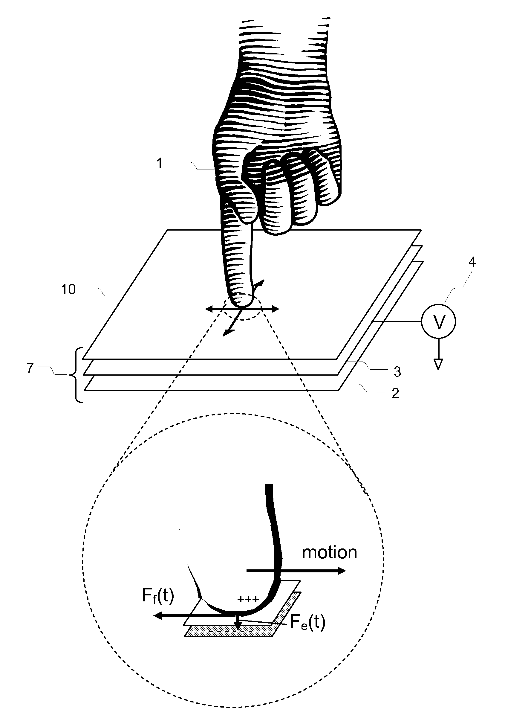
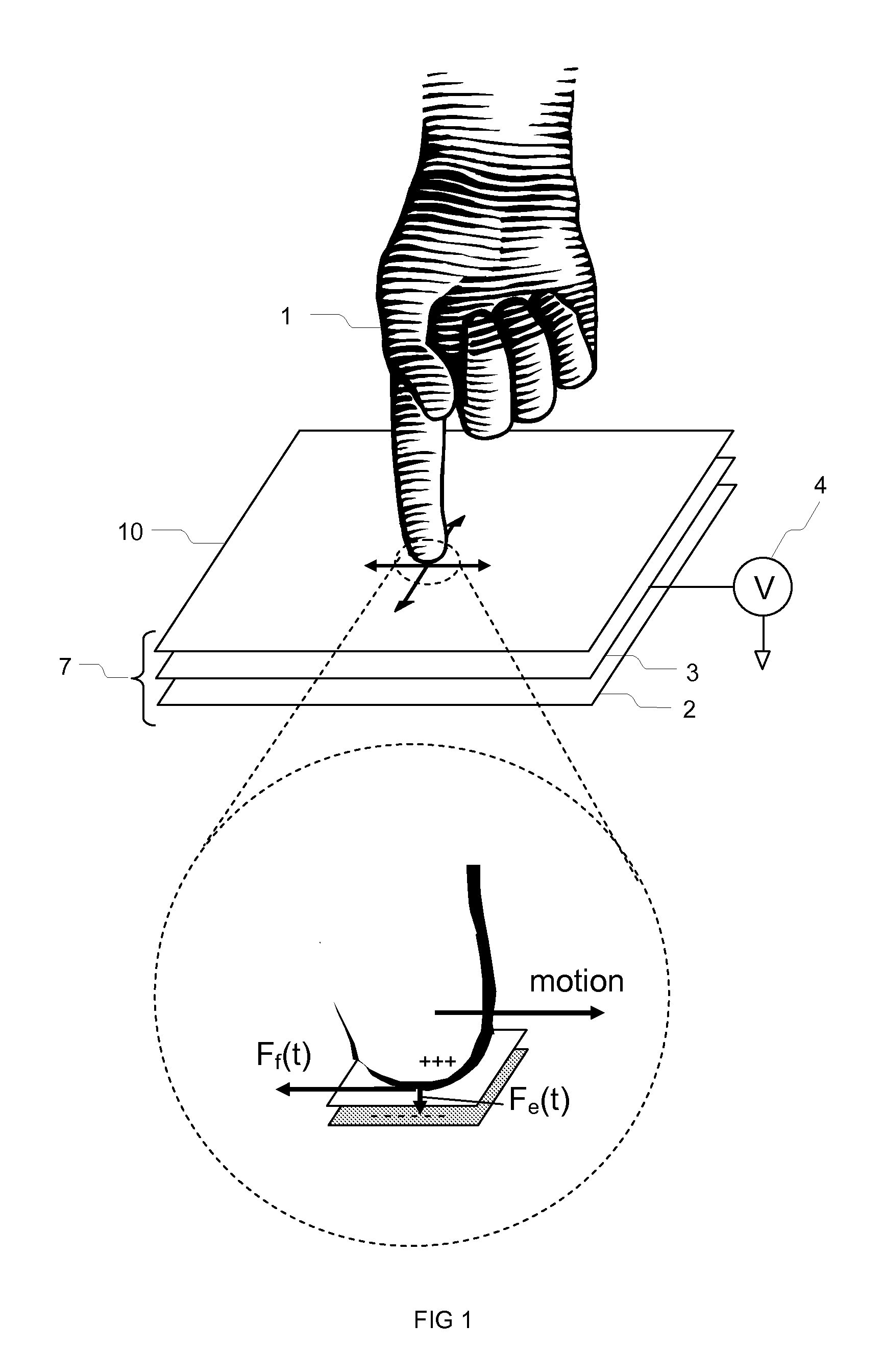
[0121]Referring to FIG. 1, tactile feedback sensations may be created by generating vibrations in the skin of a user's finger. These vibrations may be created by the electro-vibration method. A touch feedback device 7 capable of generating tactile feedback sensations by the electro-vibration method is shown in FIG. 1 and includes a conductive layer 2 and insulating layer 3 that are located beneath a surface layer 10. A voltage signal generator 4 may be attached to the conductive layer 2 and used to apply a time-varying high voltage signal. This time-varying high voltage signal may be periodic in nature, for example a sinusoid, square wave, or triangular wave. When a user 1 touches the surface layer 10 of the tactile feedback device, the skin of the finger touching the surface 10 will experience a periodically varying attractive electrostatic force Fe(t) towards the surface. This varying attractive force may cause vibrations in the users skin that are directly perceived by the user a...


PUM


Abstract

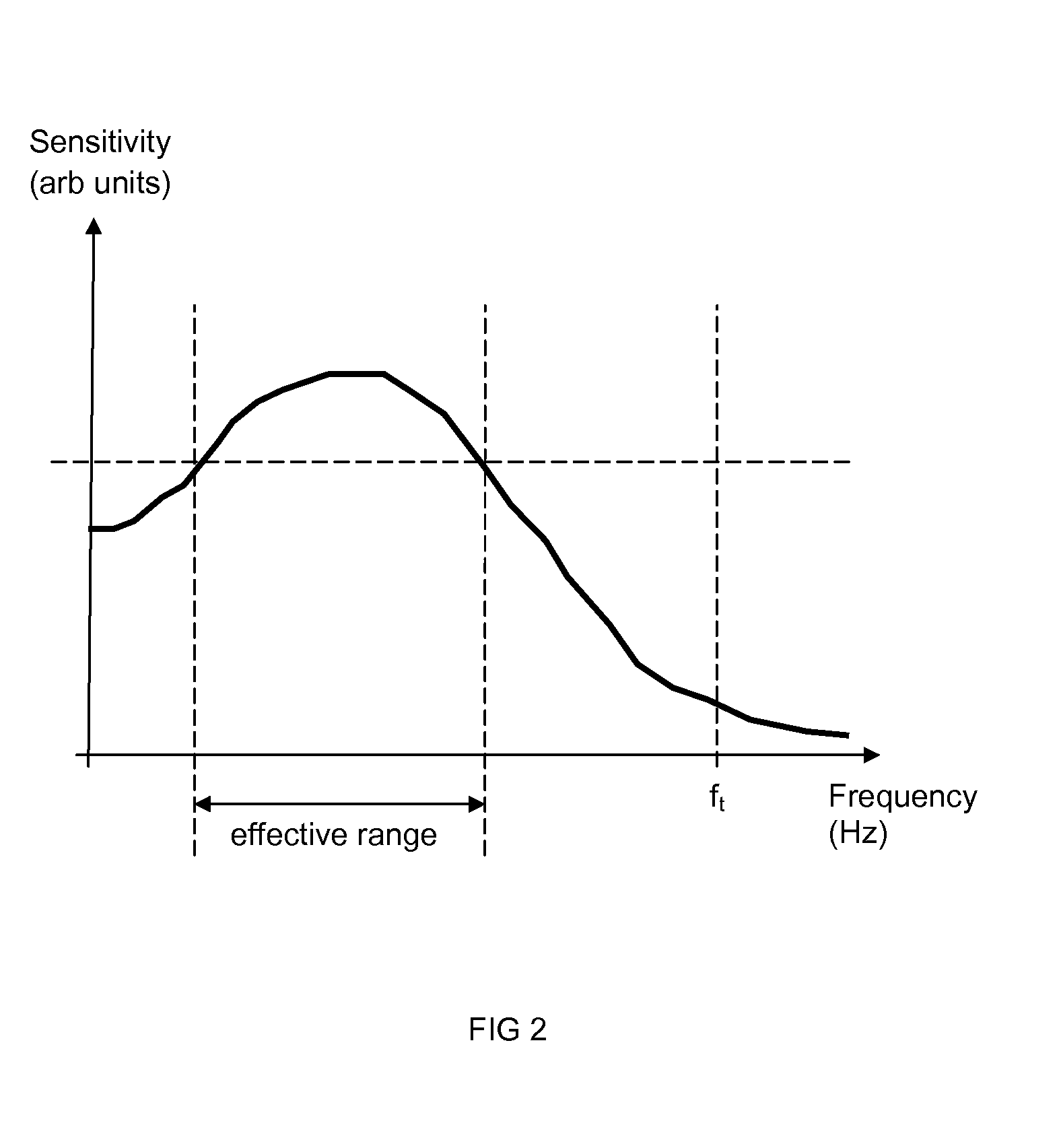
A tactile feedback actuator includes a first electrode and a second electrode separated by a gap, and a surface layer above the first and second electrodes. The first electrode receives a first stimulus voltage at a first frequency and the second electrode receives a second stimulus voltage at a second frequency, and the first and second electrodes superimpose the first and second stimulus voltages to generate a total voltage that has a beat frequency less than a perception threshold frequency. An object in contact with a portion of the surface layer is caused to vibrate at the beat frequency. The first electrode and the second electrode may constitute an electrode array including a plurality of column electrode segments, and a plurality of row electrode segments. An object in contact with a portion of the surface layer above one or more electrode segments is caused to vibrate at the beat frequency.

Description

TECHNICAL FIELD[0001]The invention relates to a tactile feedback device, and more specifically to a tactile feedback actuator that can reproduce tactile sensations at specific and multiple locations on a device surface in response to a user input. The invention further relates to a structure and control means to generate tactile sensations through electro-vibrations of the user's skin.BACKGROUND ART[0002]With touch-screen and touch-display devices (collectively referred to herein as “touch-screen devices”) rapidly growing in popularity, one significant shortcoming over traditional methods of data-entry has quickly become evident. The lack of tactile sensations perceived by the user when pressing “virtual” buttons on the touch-screen—the feelings of button edges and depressing the button for example—necessitates extra concentration by the user, who must visually confirm the position of their finger(s) relative to the display and then check they have correctly entered the data after e...

Claims


Application Information

Patent Timeline
Patent Type & Authority Applications(United States)
IPC IPC(8): G08B6/00G06F3/041
CPCG06F3/016
Inventor KARAMATH, JAMES ROBERTBROWN, CHRISTOPHER JAMESCASTILLO, SERGIO GARCIAWALTON, HARRY GARTH
Owner SHARP KK
Learn More