

Image lens system
a technology of image lens and rear group, applied in the field of image lens system, can solve the problem that the structure with only one lens element in the rear group is unfavorable for minimizing aberration
- Summary
- Abstract
- Description
- Claims
- Application Information
AI Technical Summary
Benefits of technology
Problems solved by technology
Method used
Image

Examples
first embodiment (embodiment 1)
The First Embodiment (Embodiment 1)
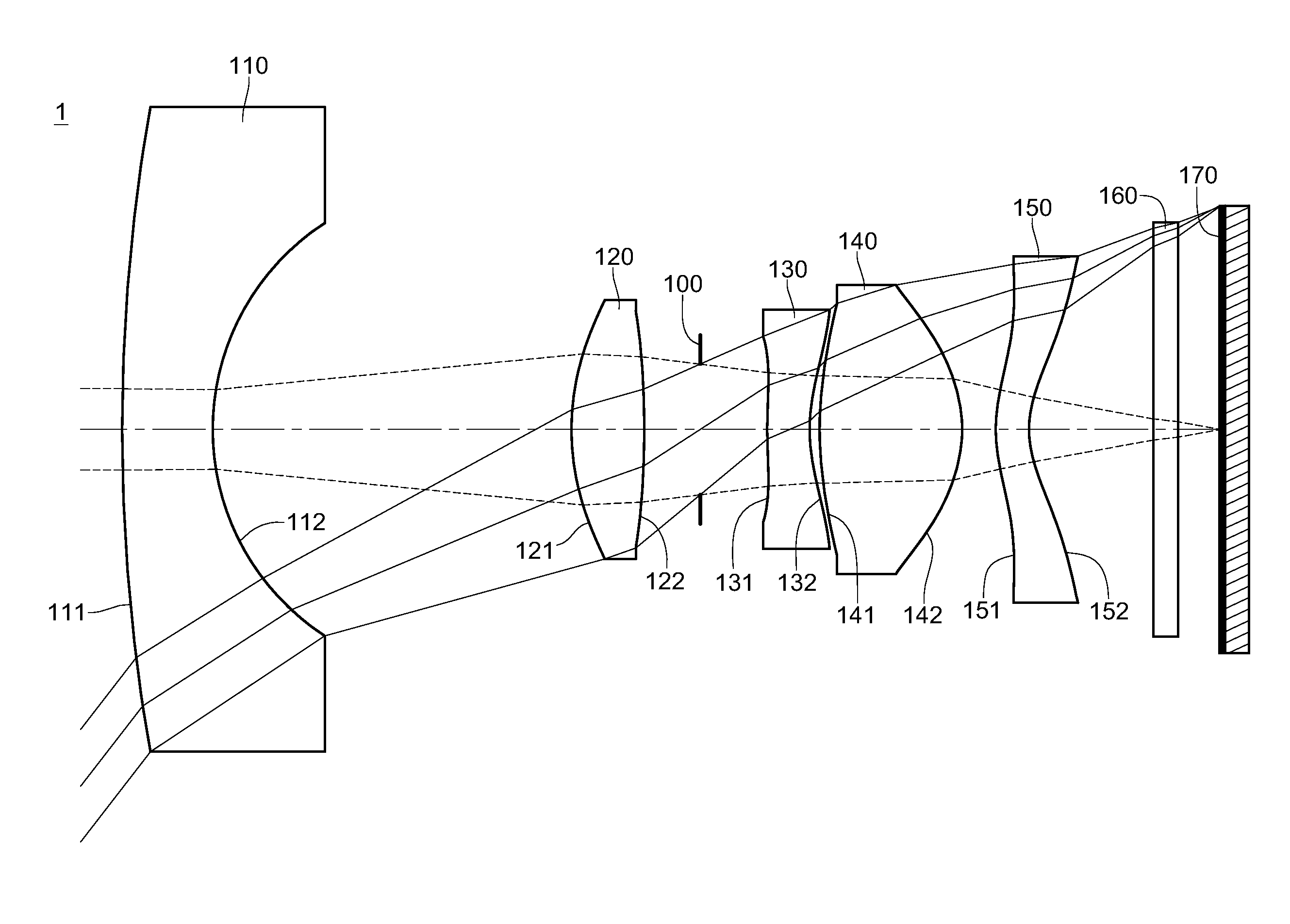
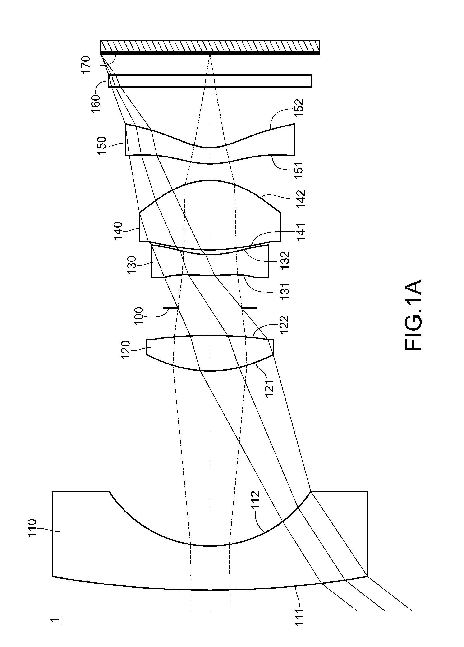
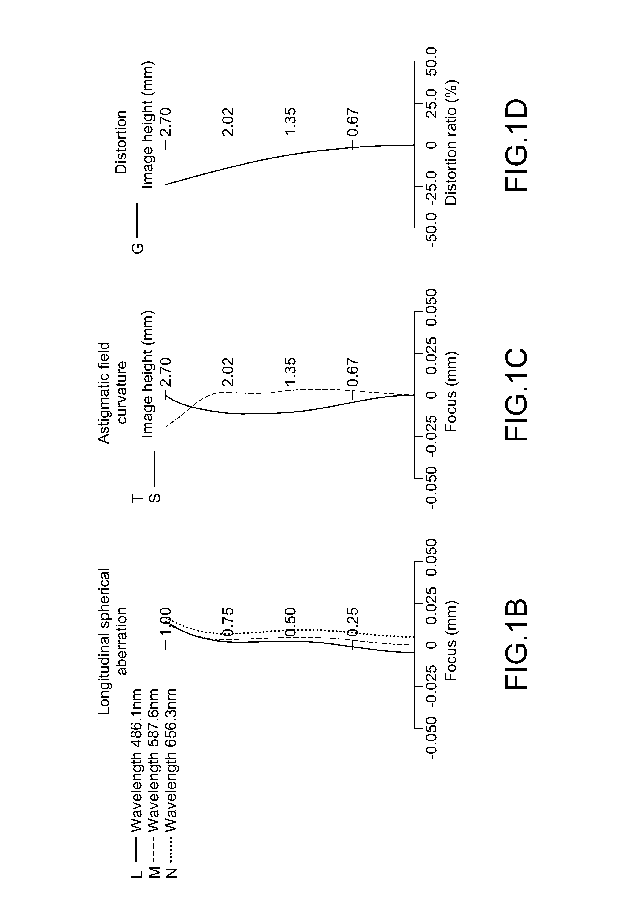
[0061]Referring to FIGs. 1A to 1D, the image lens system 1 of the first embodiment comprises, from an object side to an image side along an optical axis (from left to right in FIG. 1A) in sequence, a first lens element 110, a second lens element 120, an aperture stop 100, a third lens element 130, a fourth lens element 140, a fifth lens element 150, an IR-cut filter (infrared-cut filter) 160 and an image plane 170 including an image sensor.
[0062]The first lens element 110 with negative refractive power has a convex object-side surface 111 and a concave image-side surface 112. The second lens element 120 with positive refractive power has an aspheric convex object-side surface 121 and an aspheric convex image-side surface 122. The third lens element 130 with negative refractive power has an aspheric convex object-side surface 131 and an aspheric concave image-side surface 132. The fourth lens element 140 with positive refractive power has an aspheri...
second embodiment (embodiment 2)
The Second Embodiment (Embodiment 2)
[0068]Referring to FIGS. 2A to 2D, the image lens system 2 of the second embodiment comprises, from an object side to an image side along an optical axis in sequence, a first lens element 210, a second lens element 220, an aperture stop 200, a third lens element 230, a fourth lens element 240, a fifth lens element 250, an IR-cut filter 260 and an image plane 270 including an image sensor.
[0069]The first lens element 210 with negative refractive power has a convex object-side surface 211 and a concave image-side surface 212. The second lens element 220 with positive refractive power has an aspheric convex object-side surface 221 and an aspheric concave image-side surface 222. The third lens element 230 with negative refractive power has an aspheric convex object-side surface 231 and an aspheric concave image-side surface 232. The fourth lens element 240 with positive refractive power has an aspheric convex object-side surface 241 and an aspheric co...
third embodiment (embodiment 3)
The Third Embodiment (Embodiment 3)
[0073]Referring to FIGS. 3A to 3D, the image lens system 3 of the third embodiment comprises, from an object side to an image side along an optical axis in sequence, a first lens element 310, a second lens element 320, an aperture stop 300, a third lens element 330, a fourth lens element 340, a fifth lens element 350, an IR-cut filter 360 and an image plane 370 including an image sensor.
[0074]The first lens element 310 with negative refractive power has a convex object-side surface 311 and a concave image-side surface 312. The second lens element 320 with positive refractive power has an aspheric convex object-side surface 321 and an aspheric convex image-side surface 322. The third lens element 330 with negative refractive power has an aspheric convex object-side surface 331 and an aspheric concave image-side surface 332. The fourth lens element 340 with positive refractive power has an aspheric convex object-side surface 341 and an aspheric conve...
PUM
 Abstract
Description
Claims
Application Information