
Driving hybrid location services from WLAN stations using access points

Inactive Publication Date: 2013-11-21
QUALCOMM INC
View PDF3 Cites 46 Cited by
  • Summary
  • Abstract
  • Description
  • Claims
  • Application Information

AI Technical Summary

Benefits of technology

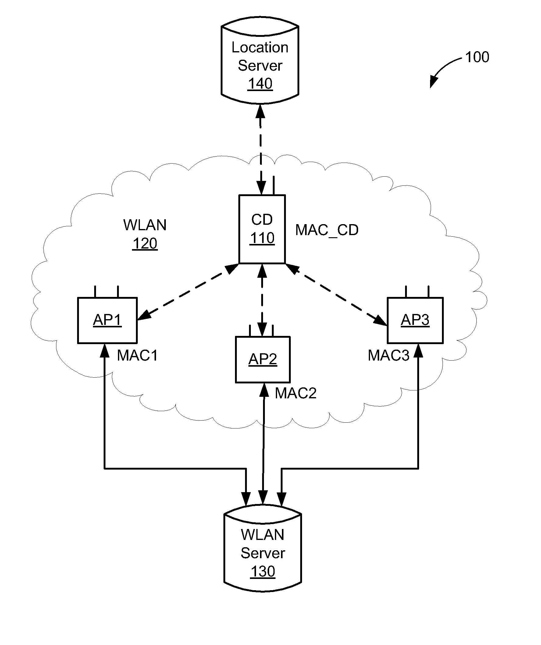
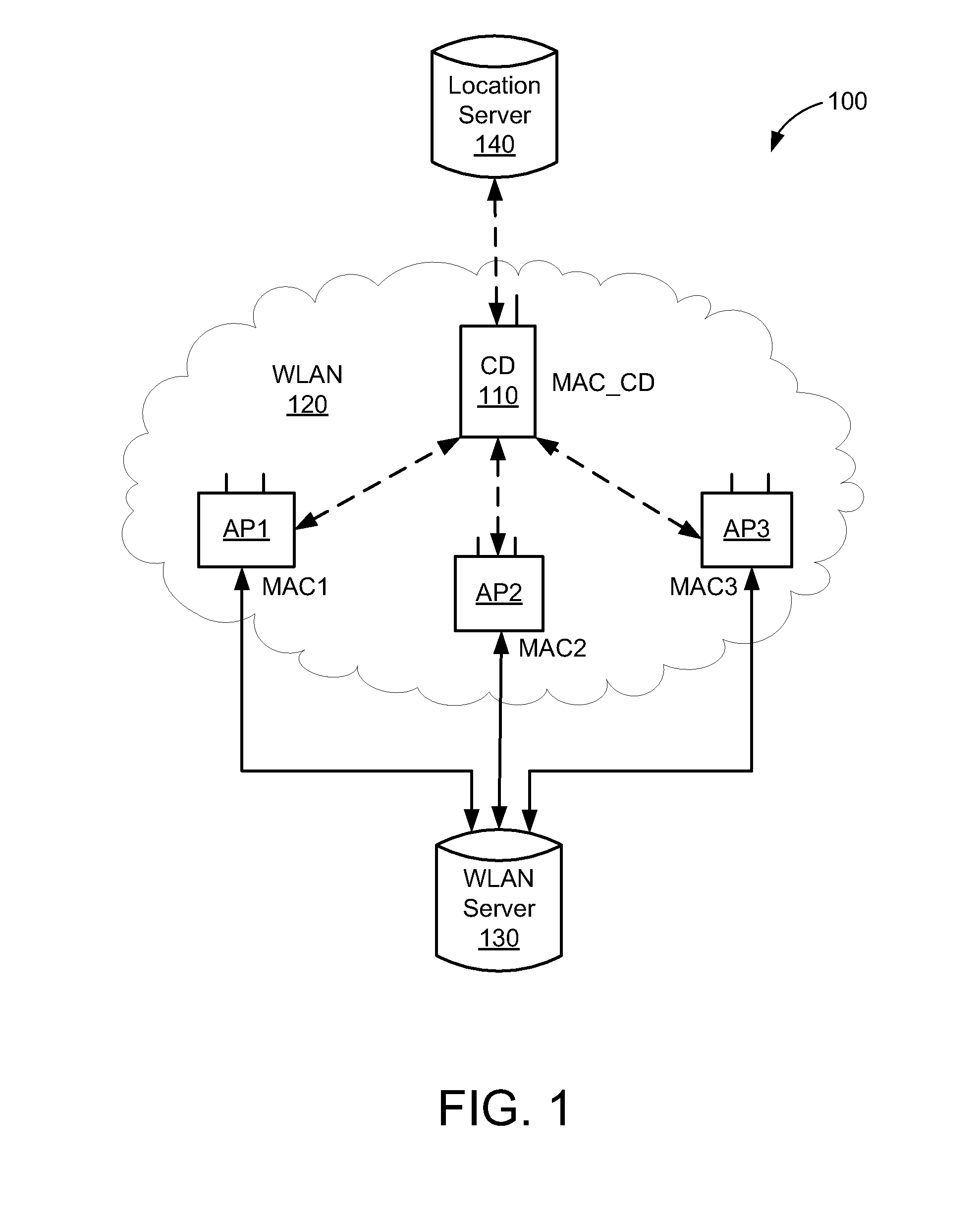
The present invention is about a WLAN system that can locate mobile devices without relying on spoofing techniques or a direct connection between the mobile device and the access point. The system works by broadcasting a modified beacon frame with vendor information from multiple access points, which the mobile device then analyzes to identify which access point is trying to locate it. The mobile device then sends a probe request frame to the identified access point, which sends an acknowledgement frame back to the mobile device. The mobile device calculates the round-trip time (RTT) between the frames and sends the information back to the access point, which may or may not use it for location-based services. The invention allows for more accurate location tracking without compromising privacy or security, and can help deliver various location-based services to the mobile device.

Problems solved by technology

Unfortunately, the accuracy of current HLS-enabled WLAN systems may be degraded when the mobile device is not responsive to request (REQ) packets or NULL frames sent by one or more of such APs.
Unfortunately, there are several problems with the WLAN central server instructing the second AP (or any AP that does not have a wireless connection established with the mobile device) to determine the location of the mobile device.
First, if the mobile device is in a power-save mode, then the spoofing technique does not work because the mobile device will not receive the spoofed NULL frame, and therefore will not respond to the second AP's spoofed NULL frame with the ACK frame.
Second, if the mobile device is off-channel when the second AP sends the spoofed NULL frame, then the mobile device may not receive the spoofed NULL frame from AP2.
Third, if the mobile device is operating in an IBSS (ad-hoc) mode, and is thus not connected to the WLAN, the mobile device will not respond to the NULL frame.

Method used


Image

  • Driving hybrid location services from WLAN stations using access points
  • Driving hybrid location services from WLAN stations using access points
  • Driving hybrid location services from WLAN stations using access points

Examples


Embodiment Construction

[0019]In accordance with the present embodiments, accurate position capability can be provided using a Wireless Local Area Network (WLAN). As used herein, the term WLAN can include communications governed by the IEEE 802.11 standards, Bluetooth, HiperLAN (a set of wireless standards, comparable to the IEEE 802.11 standards, used primarily in Europe), and other technologies having relatively short radio propagation range. Further, as used herein, the terms “mobile device” and “client device” refer to a communication device that can communicate wirelessly over an associated WLAN (and other wireless networks such as cellular and Bluetooth networks), and thus the terms are interchangeable.

[0020]In the following description, numerous specific details are set forth such as examples of specific components, circuits, and processes to provide a thorough understanding of the present disclosure. Also, in the following description and for purposes of explanation, specific nomenclature is set fo...


PUM


Abstract

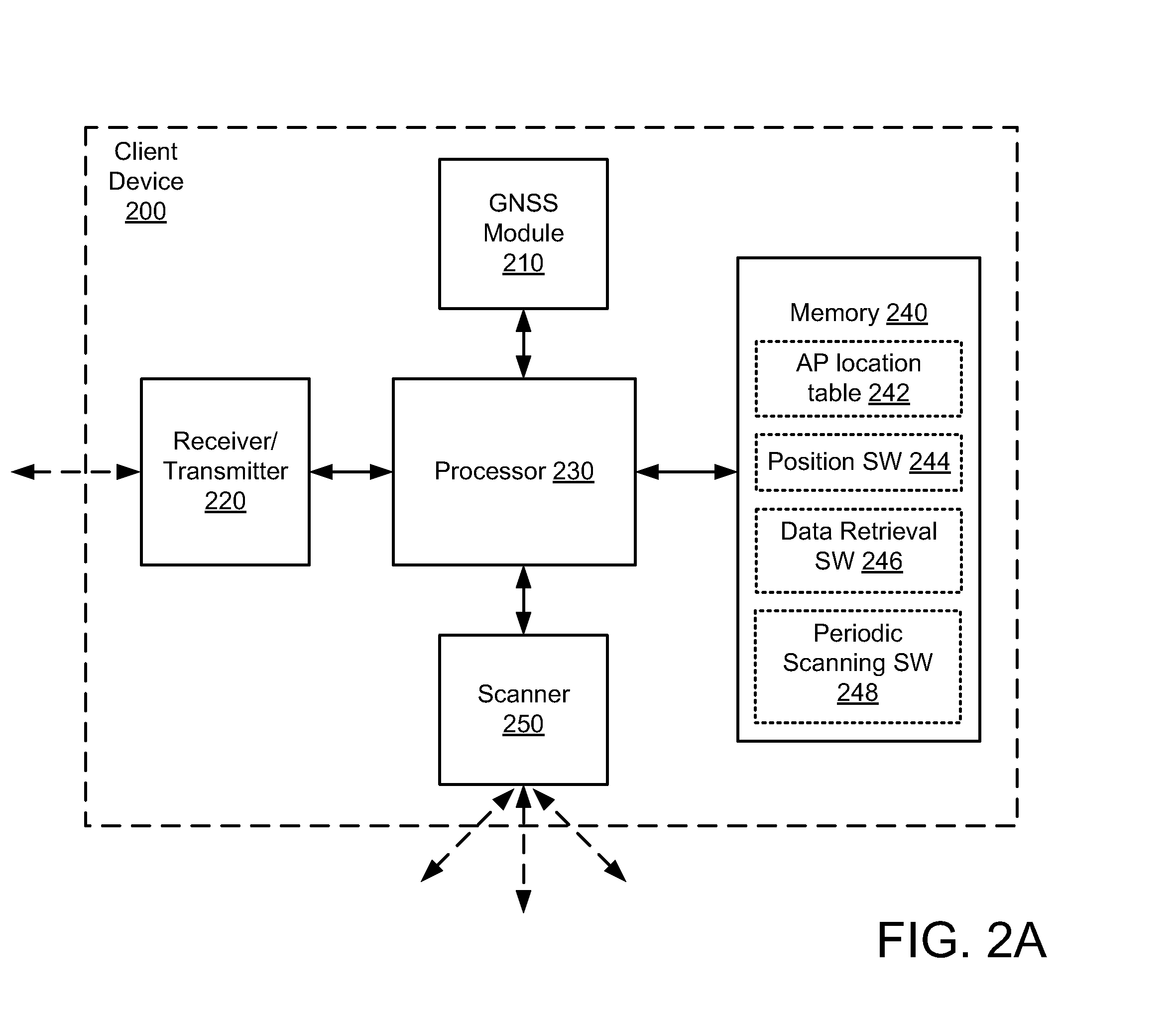
A wireless local area network (WLAN) positioning system is disclosed that allows the WLAN system to determine the location attributes of a client device operating in a power save mode, operating on a different channel than the WLAN's access points, and / or operating in an ad-hoc mode. The client device periodically performs scanning operations during which beacon frames broadcast by a selected AP(s) can be received. The client device parses information embedded in the beacon frames, and in response thereto selectively initiates ranging operations to determine its location attributes. After determining its location attributes, the client devices sends the location attributes back to the selected AP(s).

Description

TECHNICAL FIELD[0001]The present embodiments relate generally to wireless networks, and specifically to determining the location of Wi-Fi enabled wireless devices.BACKGROUND OF RELATED ART[0002]Modern navigation systems frequently use a global navigation satellite system (GNSS) for position determination. However, the recent proliferation of Wi-Fi access points in wireless local area networks (WLANs) has made it possible for navigation systems to use these access points for position determination, especially in areas where there is a large concentration of active Wi-Fi access points (e.g., urban cores, shopping centers, office buildings, and so on). Indeed, WLAN positioning systems can be advantageous over GNSS in certain environments because of GNSS signal coverage limitations. For example, while GNSS signals may not be readily detectable inside structures such as shopping malls and office buildings (e.g., due to signal attenuation and / or multipath effects), wireless signals genera...

Claims


Application Information

Patent Timeline
IPC IPC(8): H04W84/12
CPCG01S5/0236G01S5/14G01S13/876
Inventor PANNEERSELVAM, SIVAKUMAR
Owner QUALCOMM INC
Learn More