Electric power steering apparatus

a technology of electric power steering and steering gear, which is applied in the direction of steering initiation, instruments, vessel construction, etc., can solve the problems of poor steering characteristic, excessive torque derivative control level, and difficulty in achieving both suppression of reverse input vibration and excellent steering characteristic,

Active Publication Date: 2013-11-21
JTEKT CORP
View PDF25 Cites 39 Cited by
  • Summary
  • Abstract
  • Description
  • Claims
  • Application Information

AI Technical Summary

Benefits of technology

[0037]According to this structure, a phenomenon that the steering angle of the steering wheel returns to a

Problems solved by technology

Within such a range, a torque derivative control level, which has a phase advancing characteristic, becomes excessive.
According to the conventional technology disclosed in patent Document 1, however, it is difficult to accomplish both suppression of reverse input vibration and excellent steering characteristic.
In order to satisfy this requisition, when a torque derivative control level

Method used


Image

  • Electric power steering apparatus
  • Electric power steering apparatus
  • Electric power steering apparatus

Examples


first embodiment

[0053]An explanation will be given of a first embodiment that embodies an electric power steering apparatus (EPS) of the present invention with reference to FIGS. 1-9.

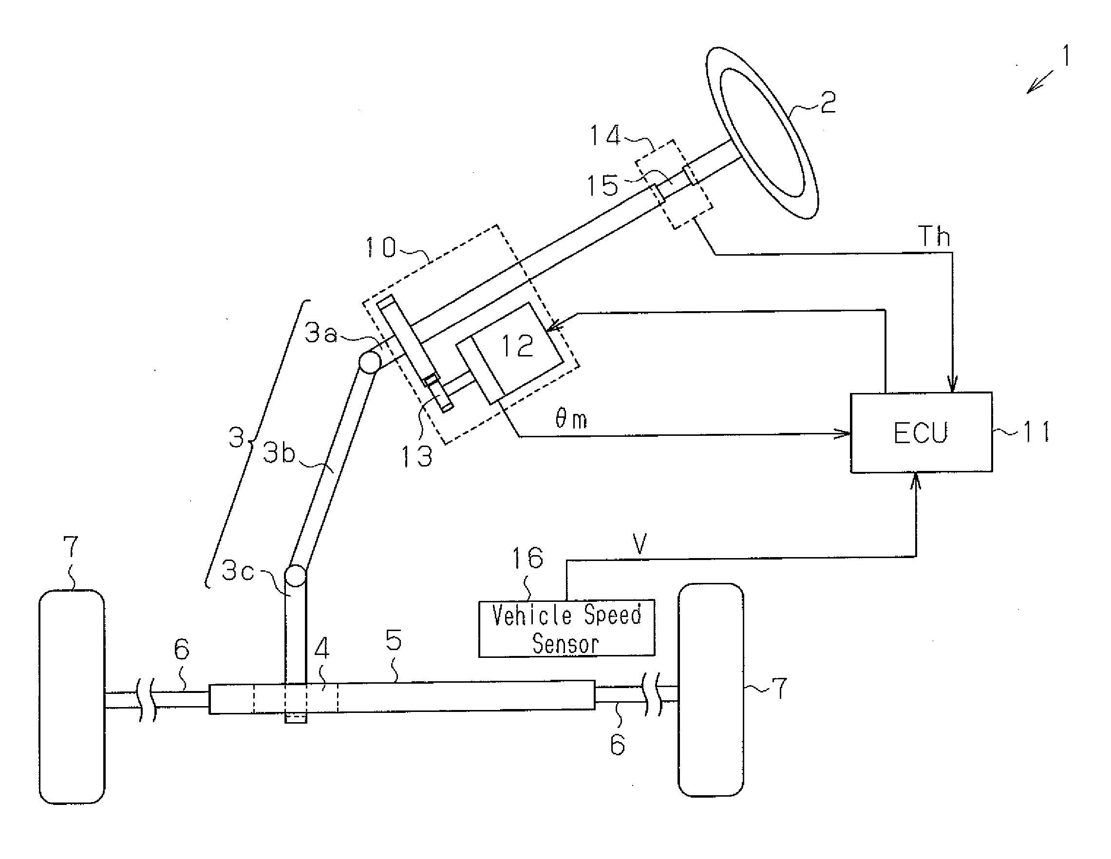
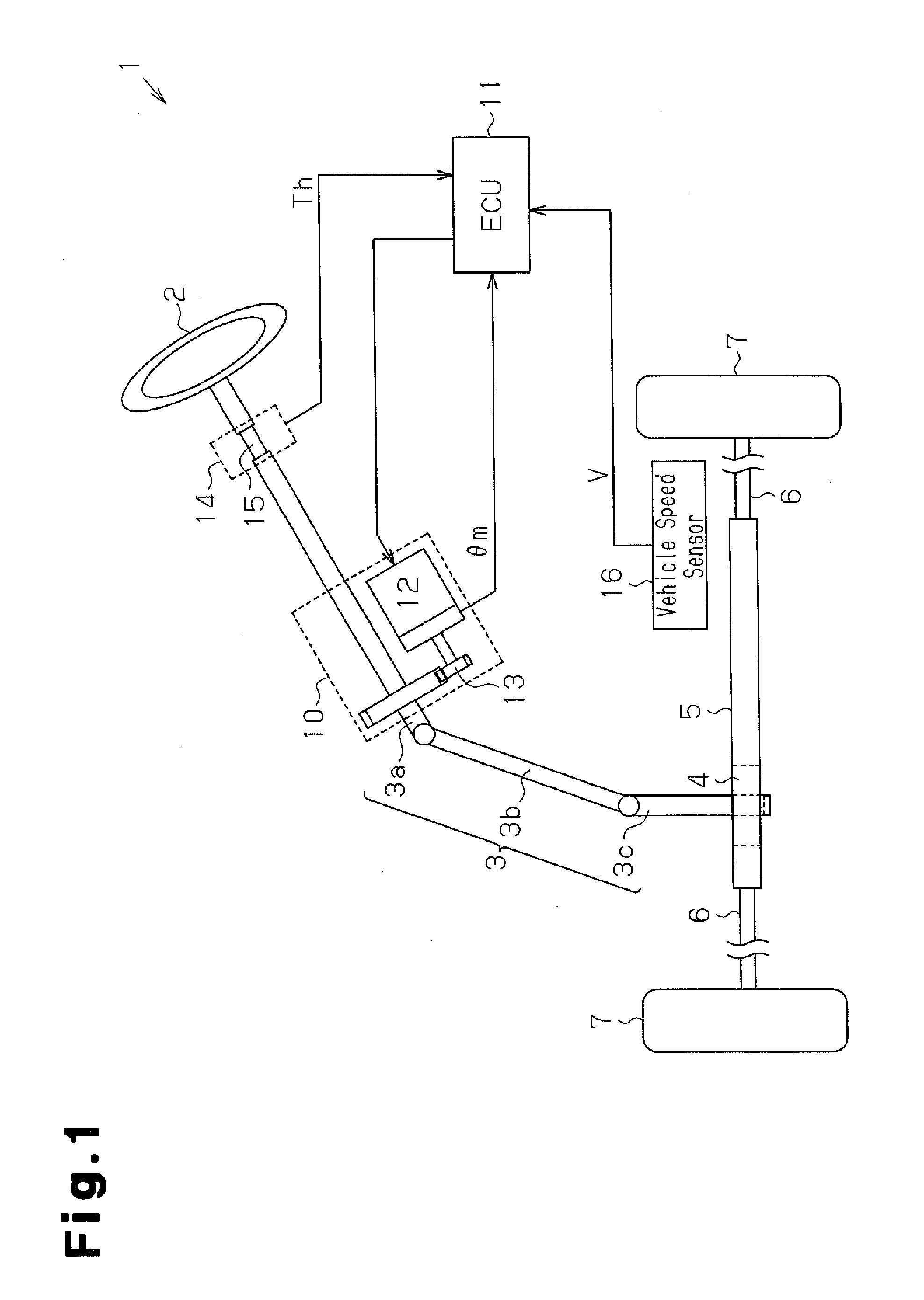
[0054]As illustrated in FIG. 1, a steering wheel 2 is fixed to a steering shaft 3. The steering shaft 3 is coupled with a rack shaft 5 through a rack and pinion mechanism 4. Together with the operation of the steering wheel 2, the steering shaft 3 rotates. The rotation of the steering shaft 3 is converted into a reciprocal linear motion of the rack shaft 5 through the rack and pinion mechanism 4. The steering shaft 3 includes a column shaft 3a, an intermediate shaft 3b, and a pinion shaft 3c coupled with each other. The reciprocal linear motion of the rack shaft 5 is transmitted to unillustrated knuckles through tie rods 6 coupled to both ends of the rack shaft 5. Accordingly, the steering angle of turning wheels 7, i.e., the traveling direction of a vehicle is changed.

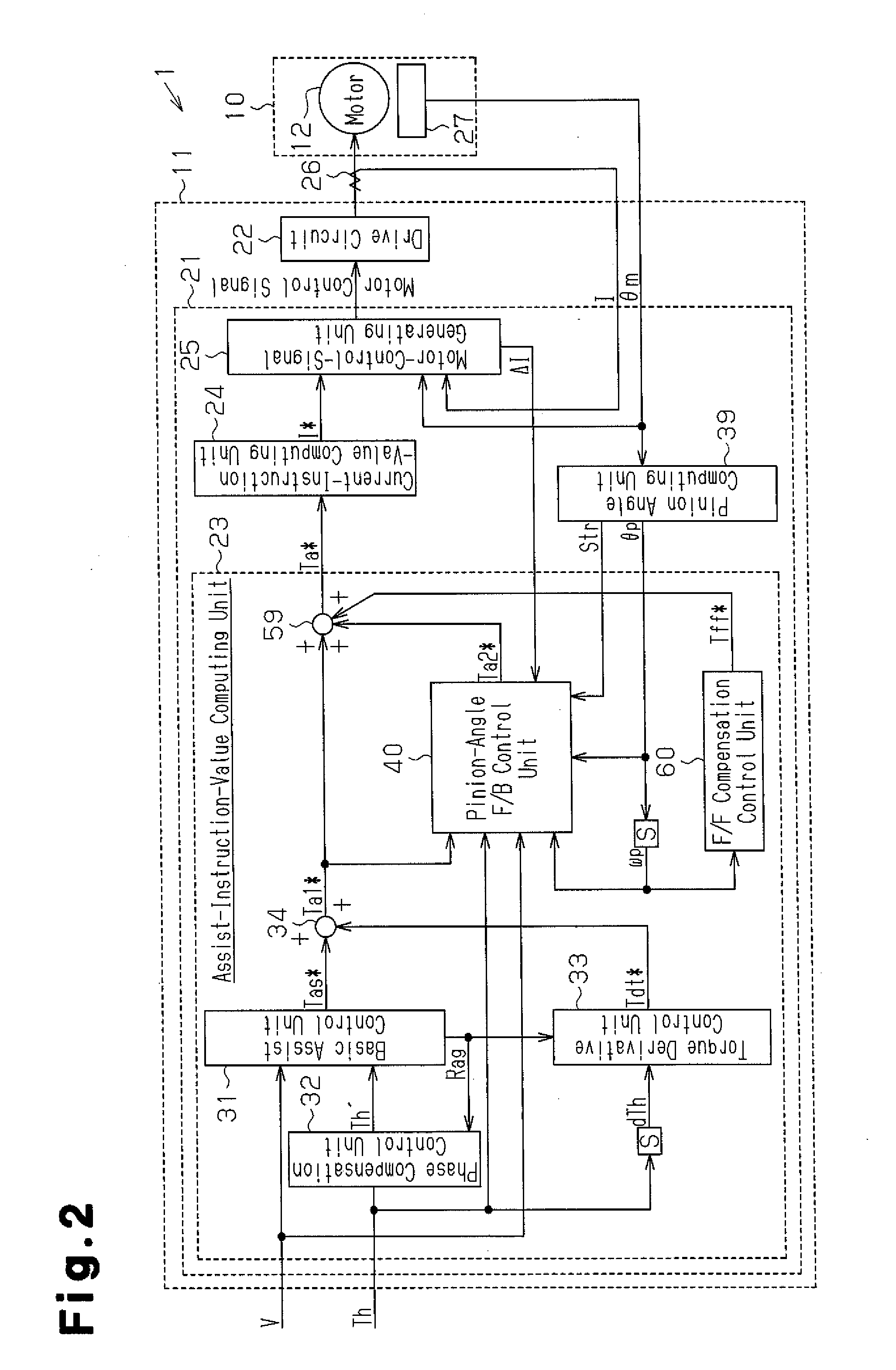
[0055]An EPS 1 includes an EPS actuator 10 that is...

second embodiment

[0098]Next, an explanation will be given of a second embodiment of the present invention with reference to FIGS. 10 to 15. In the second embodiment, the detailed explanation of the same component as that of the first embodiment will be omitted.

[0099]As illustrated in FIG. 10, an assist-instruction-value computing unit 123 includes a road-information F / B control unit 160. The load-information F / B control unit 160 calculates a road information control level Trif* that reduces the second assist component Ta2* based on the second assist component Ta2*. Moreover, the assist-instruction-value computing unit 123 includes a subtractor 161 at the downstream side over the adder 34. The subtractor 161 superimposes (subtracts) the road information control level Trif* to the first assist component Ta1*.

[0100]As illustrated in FIG. 11, the road-information F / B control unit 160 includes a road-IF-gain computing unit 162 that calculates a road IF gain Krif, and a multiplier 163. The multiplier 163 ...


PUM


Abstract

An assisting command value calculating unit calculates a first assisting factor on the basis of the value of a torque differential control volume added to a basic assist control volume based on a steering torque value, while increasing or decreasing, on the basis of an assisting gradient, the torque differential control volume based on a torque differential value. The pinion angle F/B control unit calculates a pinion angle command value, capable of being converted to a steering angle of the steering wheel, on the basis of the steering torque and the first assisting factor, and executes rotational angle feedback control. The assisting command value calculating unit calculates an assisting command value on the basis of the value of a second assisting factor, calculated by the pinion angle F/B control unit, added to the first assisting factor.

Description

TECHNICAL FIELD[0001]The present invention relates to an electric power steering apparatus.BACKGROUND ART[0002]Conventionally, electric power steering apparatus (EPS) having a motor as a drive source are known. For EPS, various technologies are proposed which utilize a high controllability to realize an excellent steering feeling.[0003]For example, an EPS disclosed in Patent Document 1 optimizes the characteristic of compensation control of each kind based on an assist gradient that is a ratio of a change in an assist force relative to a change in steering torque. That is, the EPS calculates a torque derivative control level that is a compensation component based on the derivative of steering torque. Next, the EPS adds the compensation component to the basic component of an assist instruction value corresponding to a target assist force. Hence, the responsiveness of applying an assist force relative to a change in the steering torque can be enhanced. Accordingly, a response delay of...

Claims


Application Information

Patent Timeline
IPC IPC(8): B62D5/04
CPCB62D5/0472B62D5/0463B62D6/08
Inventor TAMAIZUMI, TERUTAKAEKI, HIROZUMIKITA, MASAYUKINAMIKAWA, ISAO
Owner JTEKT CORP
Why Eureka
Try Eureka