Ultrasonic flow rate measurement device

a flow rate measurement and ultrasonic technology, applied in measurement devices, volume/mass flow measurement, instruments, etc., can solve the problems of reducing the drive input of ultrasonic, increasing the cost, and difficulty in reducing power consumption, so as to prevent an increase in cost, stabilize measurement accuracy, and suppress the disturbance of fluids

Active Publication Date: 2013-11-28
PANASONIC INTELLECTUAL PROPERTY MANAGEMENT CO LTD
View PDF6 Cites 16 Cited by
  • Summary
  • Abstract
  • Description
  • Claims
  • Application Information

AI Technical Summary

Benefits of technology

[0013]With this configuration, the suppressing member for restricting a fluid from intruding into the sensor fixing cavity is molded at the same time when the sensor fixing casing is molded. Therefore, it is possible to prevent an increase in cost or an increase in the number of assembling man-hours without disposing a separate member, thus suppressing disturbance of a fluid to be measured, which may be produced in the sensor fixing cavity, so as to stabilize measurement accuracy and reduce power consumption.

Problems solved by technology

However, the above-described configurations require separate members, and therefore, there arises a problem of an increase in cost due to an increase in material cost or number of man-hours.
In addition, a reception level of an ultrasonic wave in ultrasonic sensors 122a and 122b drops, and therefore, there arises a problem of difficulty of reduction of a drive input into ultrasonic sensors 122a and 122b. In view of this, when a gas meter for measuring domestic fuel gas such as town gas or LPG (liquefied petroleum gas) is kept to be used with a small battery capacity for as long a period as ten years, there arises a problem of difficulty in reducing power consumption.

Method used


Image

  • Ultrasonic flow rate measurement device
  • Ultrasonic flow rate measurement device
  • Ultrasonic flow rate measurement device

Examples


first exemplary embodiment

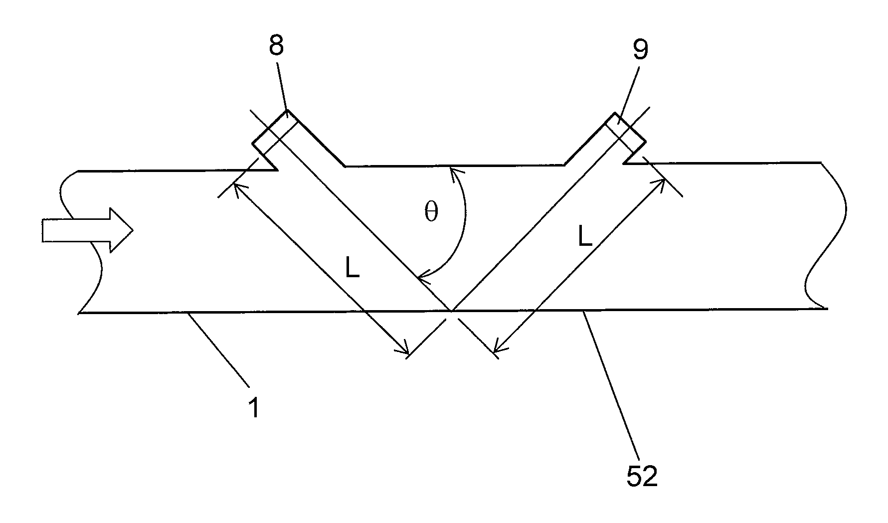
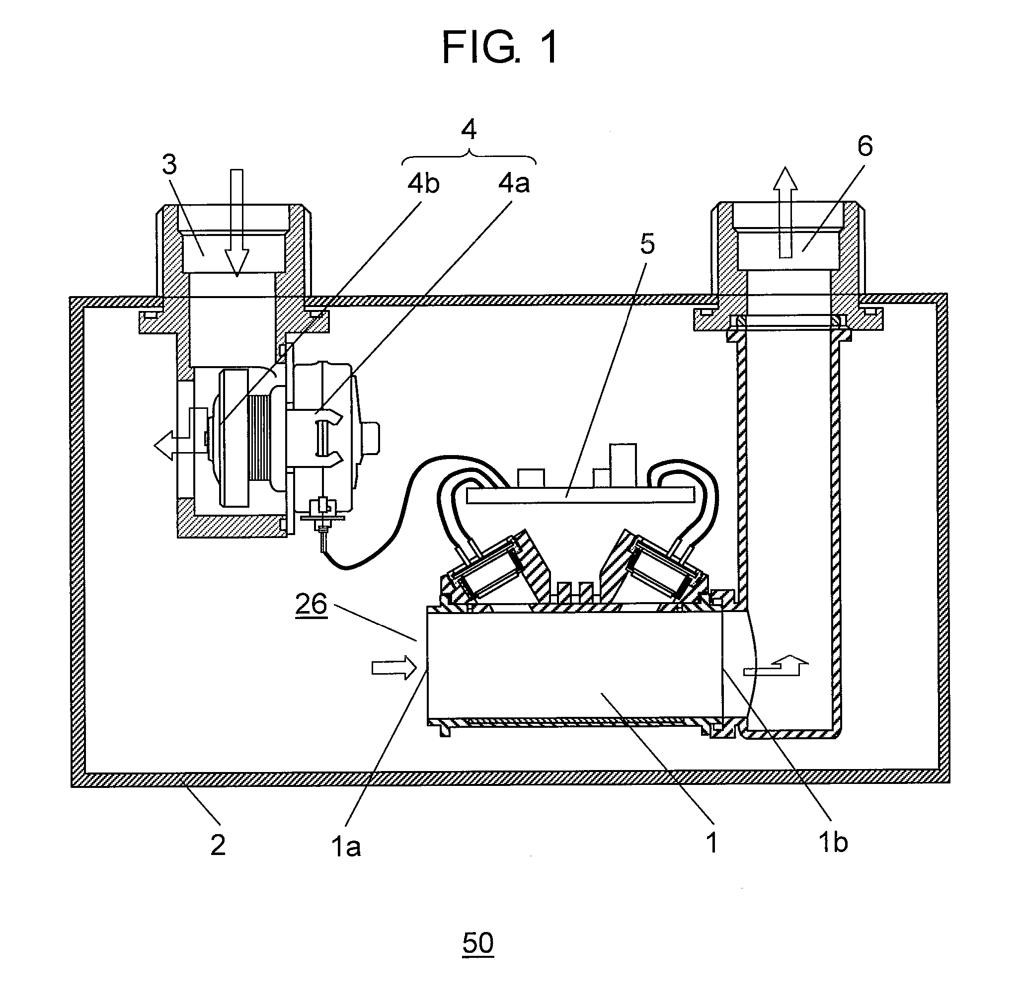
[0030]FIG. 1 is a cross-sectional view showing the configuration of ultrasonic flow rate measurement device 50 in an exemplary embodiment according to the present invention. In FIG. 1, hollow arrows indicate flows of a fluid (i.e., a fluid to be measured).

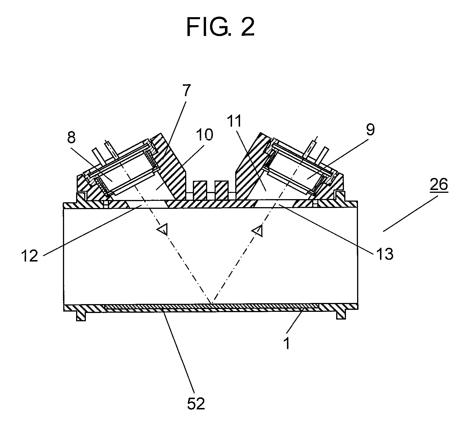
[0031]As shown in FIG. 1, ultrasonic flow rate measurement device 50 is provided with fluid supply path 3. Fluid supply path 3 is provided with, on the way of a channel, cutoff valve 4 including drive 4a having an electromagnet device such as a stepping motor and valve body 4b in association with drive 4a, wherein valve body 4b is adapted to open or close cutoff valve 4. When cutoff valve 4 is released, a fluid to be measured is allowed to flow from fluid supply path 3 into meter casing 2. Ultrasonic flow rate measurement device 50 is provided with measurement channel 1, through which the fluid to be measured flows. Measurement channel 1 is formed into a rectangular shape in cross section such as a rectangle. The fluid to be measur...

second exemplary embodiment

[0064]FIG. 11 is a perspective view showing the configuration of slider die 32 in a second exemplary embodiment according to the present invention. FIG. 12 is a perspective view showing the configuration of sensor fixing casing 7 in the second exemplary embodiment according to the present invention.

[0065]The configurations of ultrasonic flow rate measurement device 50 and a die in the present exemplary embodiment are the same as those in the first exemplary embodiment except the configuration of slider die 32, and therefore, their explanations will be omitted.

[0066]As shown in FIG. 11, grid-like slits 33 are formed at the tip of slider die 32 in the present exemplary embodiment. Slits 33 are formed perpendicularly to a flow inside of measurement channel 1. Slits 33 are configured such that their depth direction is perpendicular to the ultrasonic wave emission surfaces of a pair of ultrasonic sensors 8 and 9. Grid-like suppressing member 34 after being molded is opened perpendicularl...


PUM


Abstract

An ultrasonic flow rate measurement device includes a measurement channel, through which a fluid to be measured flows; and a sensor fixing casing having openings formed in the measurement channel and sensor fixing cavities communicating with the openings. Moreover, the ultrasonic flow rate measurement device includes a pair of ultrasonic sensors contained in the sensor fixing cavities, for measuring the flow rate of the fluid to be measured; and a flow rate measuring unit for detecting the flow rate based on an ultrasonic wave propagation time between the pair of ultrasonic sensors. Furthermore, the ultrasonic flow rate measurement device includes a suppressing member formed at each of the openings, for suppressing the fluid to be measured from intruding into each of the sensor fixing cavities, wherein the suppressing member is molded integrally with the sensor fixing casing.

Description

TECHNICAL FIELD[0001]The present invention relates to an ultrasonic flow rate measurement device for measuring the flow rate of gas or the like.BACKGROUND ART[0002]Explanation will be made on a conventional ultrasonic flow rate measurement device.[0003]FIG. 14 is a view showing the cross-sectional configuration of conventional ultrasonic flow rate measurement device 100.[0004]As shown in FIG. 14, ultrasonic flow rate measurement device 100 is provided with flow rate measuring tube 121 that allows a fluid to be measured to flow from one side to the other side. Moreover, ultrasonic sensor 122a is disposed on an upstream side whereas another ultrasonic sensor 122b is disposed on a downstream side, wherein ultrasonic sensors 122a and 122b are disposed opposite to each other while holding flow rate measuring tube 121 therebetween at a predetermined angle with respect to the center line.[0005]Ultrasonic sensors 122a and 122b are contained in recesses 125a and 125b formed in the flow rate ...

Claims


Application Information

Patent Timeline
Patent Type & Authority Applications(United States)
IPC IPC(8): G01F1/66
CPCG01F1/66G01F1/662G01F15/14
Inventor MIYATA, HAJIMENAKANO, MAKOTOFUJII, YUJIOZAKI, YUKINORI
Owner PANASONIC INTELLECTUAL PROPERTY MANAGEMENT CO LTD
Why Eureka
Try Eureka