Operating switch

a technology of operating switch and power seat, which is applied in the direction of contact form, pulse technique, transportation and packaging, etc., can solve the problems of power seat malfunction, and achieve the effect of effective absorption of electromagnetic waves

a technology of operating switch and power seat, which is applied in the direction of contact form, pulse technique, transportation and packaging, etc., can solve the problems of power seat malfunction, and achieve the effect of effective absorption of electromagnetic waves

US20130313099A1Inactive Publication Date: 2013-11-28TOYOTA BOSHOKU KK

Image

  • Operating switch
  • Operating switch
  • Operating switch

Examples


Embodiment Construction

[0018]One embodiment of the invention will be described in detail, with reference to the drawings.

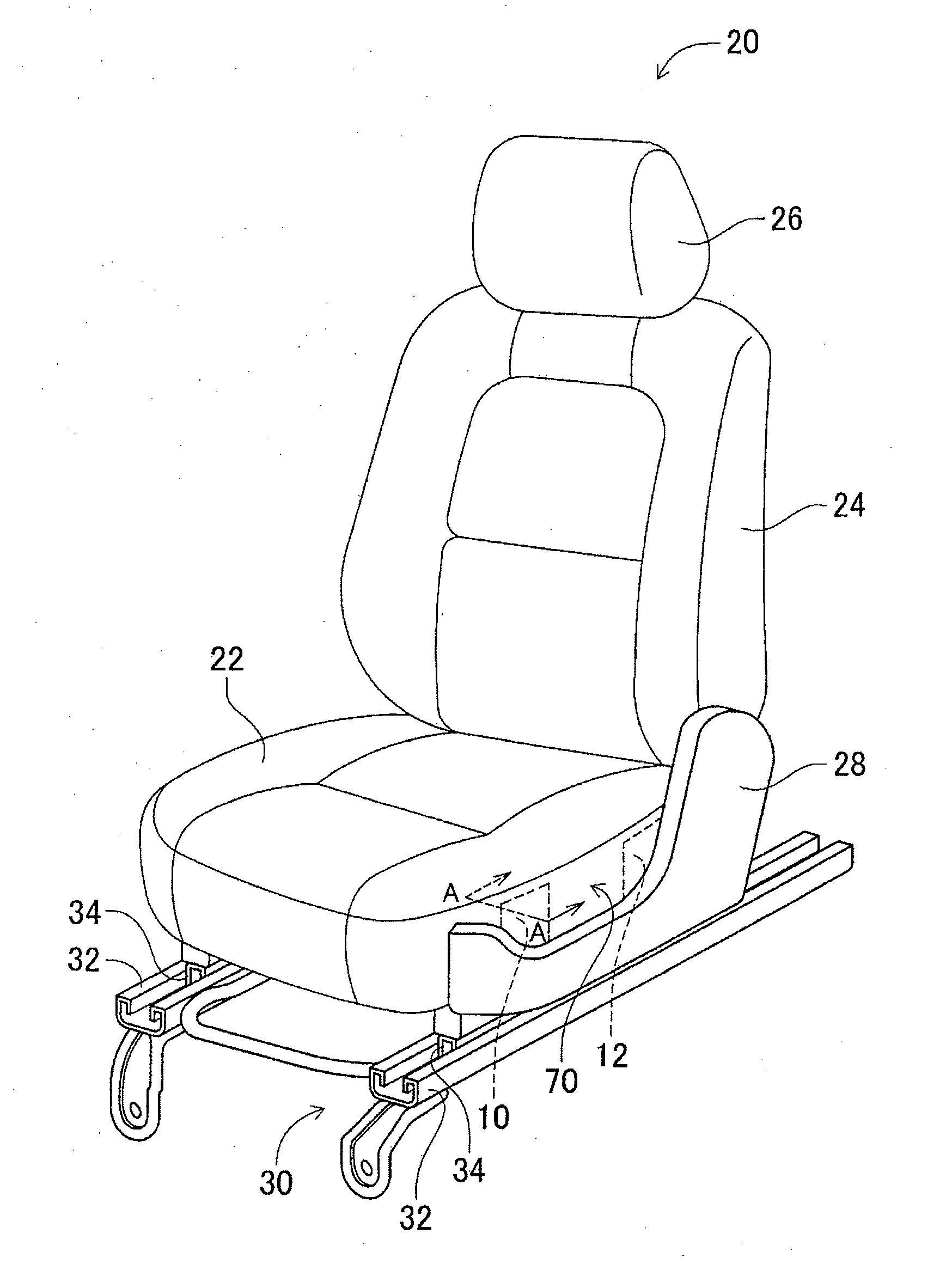
[0019]In FIG. 1, a vehicle seat 20 provided with a pair of operating switches 10, 12 according to one embodiment of the invention is illustrated as seen from a viewpoint located diagonally to the front of the seat. The vehicle seat 20 consists principally of a seat cushion 22 that supports the hips of a driver, a seat back 24 that supports the back of the driver, a head rest 26 provided on the upper end of the seat back 24 for supporting the head of the driver, and a side shield 28 that covers a side face of the seat cushion 22. The vehicle seat 20 is constructed as a so-called power seat, of which various seating positions or postures can be electrically adjusted, and each of the operating switches 10, 12 is operable to adjust the position of the vehicle seat 20 in the longitudinal direction.

[0020]A slide mechanism 30 is employed as a mechanism for changing the position of the vehicle ...


PUM


Abstract

An operating switch provided on a vehicle seat includes a first conductive cloth that includes a wire material that is able to carry current, and functions as a touch sensor that detects an input medium approaching or contacting with the conductive cloth, a second conductive cloth provided below the first conductive cloth and capable of absorbing electromagnetic wave, and an insulating cloth inserted between the two conductive cloths. The second conductive cloth absorbs electromagnetic waves, and can prevent malfunction of the first conductive cloth that functions as a touch sensor.

Description

INCORPORATION BY REFERENCE[0001]The disclosure of Japanese Patent Application No. 2012-120912 filed on May 28, 2012 including the specification, drawings and abstract is incorporated herein by reference in its entirety.BACKGROUND OF THE INVENTION[0002]1. Field of the Invention[0003]The invention relates to an operating switch, and more particularly to an operating switch provided on a vehicle seat.[0004]2. Description of Related Art[0005]One type of vehicle seat, such as a power seat, is equipped with a mechanism for electrically adjusting the seat position, and another type of vehicle seat is equipped with a mechanism, such as a seat heater, for adjusting the seat temperature. In these types of vehicle seats, an operating switch may be provided for operating each of the mechanisms. In recent years, a sheet-shaped member having electric conductivity has been developed, and a technology of providing the sheet-shaped member having conductivity on a vehicle seat and using the sheet-sha...

Claims


Application Information

Patent Timeline
28 Nov 2013
Publication
US20130313099A1
IPC
H01H1/64; B60N2/90
CPC
H01H1/64; H01H13/704; H01H2203/0085; H01H2300/008; B60N2/0228; B60N2/0239; B60N2210/12; B60N2/0231
Inventors
KOMAKI, SHINICHIRO; MURAHATA, HIROSHI