

Detecting method and device for suppressing interference of low-frequency noise
a low-frequency noise and interference detection technology, applied in the field of signal retrieval modules, can solve problems such as errors in the determination of the location of external conductive objects, signal may become distorted,
- Summary
- Abstract
- Description
- Claims
- Application Information
AI Technical Summary
Benefits of technology
Problems solved by technology
Method used
Image

Examples
first embodiment
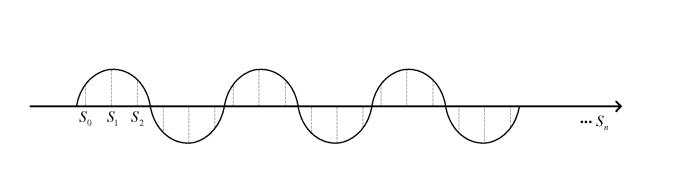
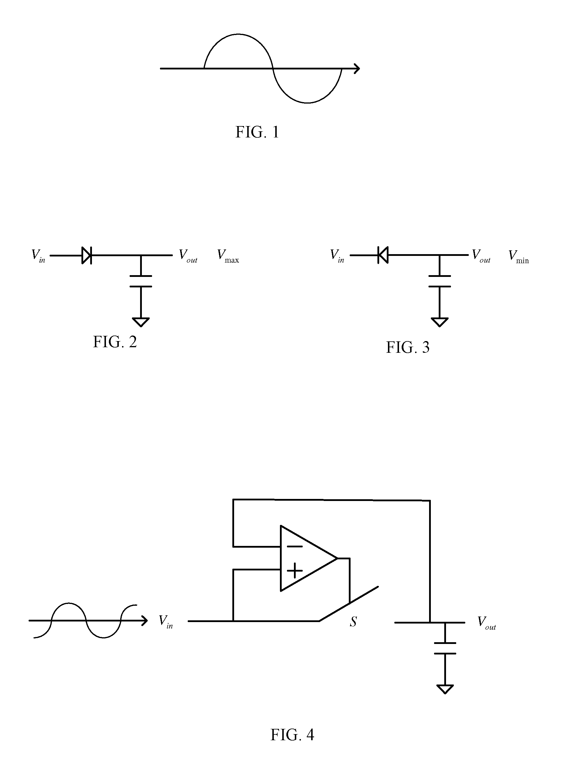
[0006]In the prior art, an input signal may be easily interfered by low-frequency noise. Referring to FIGS. 2 and 3, signal filtering circuits in accordance with the present invention are shown. To address the noise interference issue described in the prior art, the present invention proposes that a plurality of cycles of the input signal is detected in each detection instance, and only the maximum and the minimum signals in each cycle are detected.
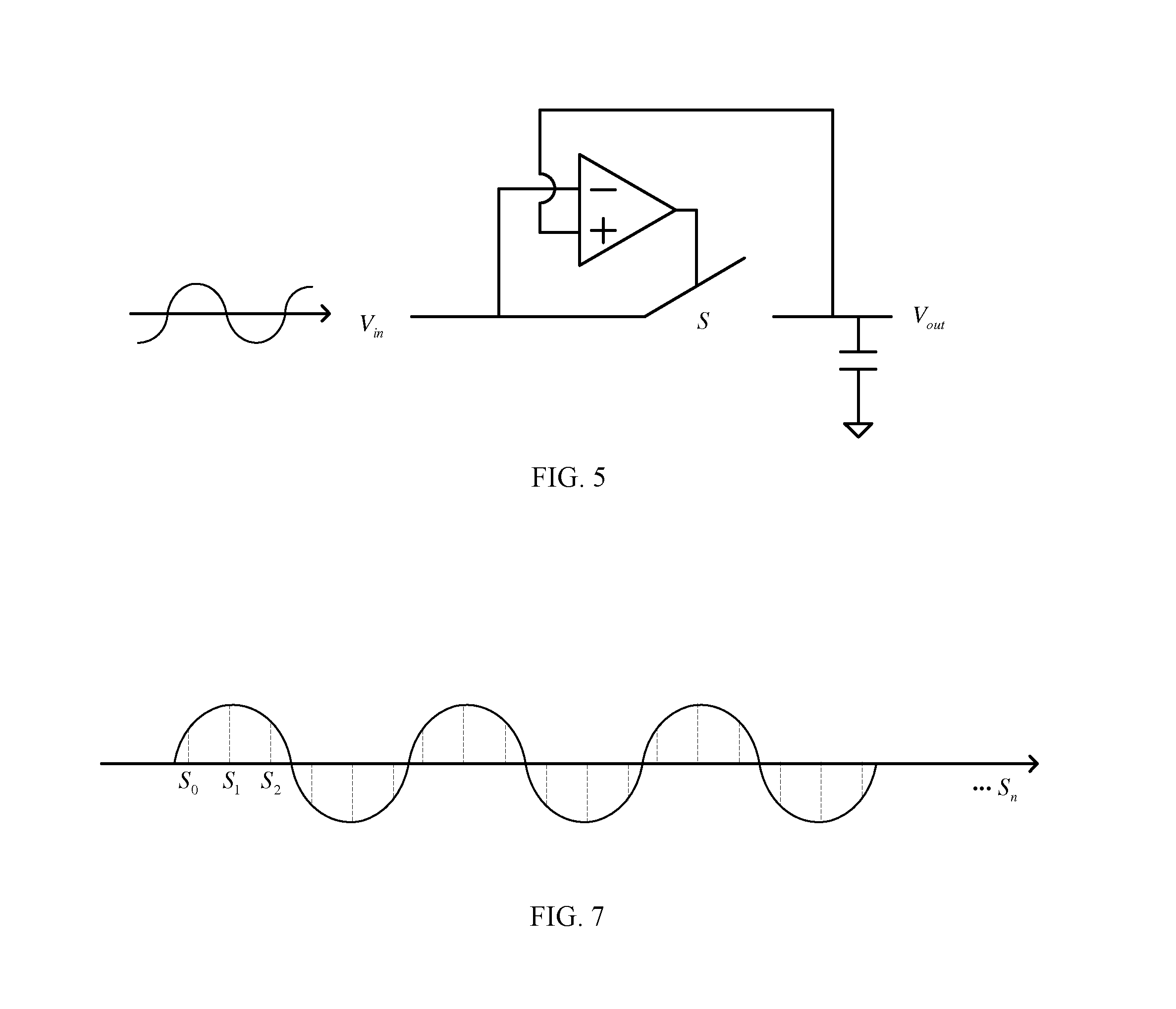
[0007]When the input signal is affected by low-frequency noise, the input signal is carried on the low-frequency signal, so the input signal will undulate with the low-frequency noise. Assuming that the difference between the amounts of interferences experienced by the first half and the second half of each cycle by the low-frequency noise is small, then the difference between the signal difference between the maximum and the minimum signals within the same cycle when the low-frequency noise is present and the signal difference between th...
third embodiment
[0026]Referring now to FIG. 9, an active capacitive pen 9 in accordance with the present invention is shown. The active capacitive pen 9 includes an internal coil 91, a rectifier 92, a DC converter 93, an AC signal generator 94 and a signal transmitting end 95.
[0027]The internal coil 91 can obtain an input signal through electromagnetic induction via an external coil 97, which serves as the power supply for the active capacitive pen. The input signal may be provided via the rectifier 92 (e.g. a bridge rectifier) to the DC converter 93 (e.g. a low dropout regulator) for providing a DC signal. The AC signal generator 94 (e.g. a “555 calculator”) provides an AC signal by using the DC signal as the power supply, and the AC signal is sent out through the signal transmitting end 95. In an example of the present invention, a voltage booster (such as a level shifter) can be added between the AC signal generator 94 and the signal transmitting end 95 to increase the electric potential of the ...
second embodiment
[0030]The above provision of the location of a hand may include the provision of a plurality of locations approached or touched by hand(s). In addition, the detecting circuit may detect the AC signal (the input signal) sent by the active capacitive pen 9 according to the first or the Without the need for an internal power supply (e.g. a battery), the active capacitive pen 9 of the present invention can be made very thin and light, and no complicated circuit is required for synchronization with the detecting circuit. The present invention thus has the advantages of a simple structure and high applicability.
[0031]Moreover, the active capacitive pen may further include a tilt switch for detecting the degree of tilt of the active capacitive pen and turning on / off the power of the active capacitive pen based on the degree of tilt. For example, when the active capacitive pen is placed flat or close to horizontal, for example, at an angle of less than 30 degrees with the horizontal line, ...
PUM
 Abstract
Description
Claims
Application Information