Simultaneous Display Video Laryngoscope And Video Stylet

a laryngoscope and video technology, applied in the field of video laryngoscope and video stylet, can solve the problems of restricted view, insertion of tubes, damage to vocal cords, etc., and achieve the effect of a wider field of view

Inactive Publication Date: 2013-11-28
KARL STORZ ENDOVISION INC
View PDF25 Cites 60 Cited by
  • Summary
  • Abstract
  • Description
  • Claims
  • Application Information

AI Technical Summary

Benefits of technology

[0011]It is therefore desired to provide an improved video laryngoscope system that provides the user with a greater field of view.
[0012]It is also desired to provide an improved video laryngoscope system that allows the user to see virtually all of the larynx and the trachea as the ETT is advanced.
[0013]It is further desired to provide an improved video laryngoscope system that facilitates a quicker intubation and reduces the probably of injuring the patient.

Problems solved by technology

However, the insertion of the tube involves risks, such as, damage to the vocal cords and a prolonged intubation procedure in which the patients breathing is stopped but oxygen is not yet delivered to the patient as the tube has not yet been inserted.
Some of the difficulties the user encounters include: the restriction of view as the tube is inserted, variations in the anatomy of the patients, an uncomfortable and unnatural position for the anesthesiologist while holding the instrument and the necessity for rapid intubation.
However, typically the view provided by the equipment has been limited requiring more time for the user to intubate the patient.
While this configuration for a video laryngoscope does provide a user very useful information in the form of image data, a major problem with current systems is the limited field of view.
So, a major problem with current systems is two-fold, 1) if the stylet is not provided with the proper angulation or bend radius prior to insertion of the ETT, the user must remove the ETT and bend the stylet to match the patient's particular anatomy (which takes additional time and is highly undesirable); and 2) as the ETT (and stylet) is advanced through the vocal cords, the view in front of the ETT blocked by the stylet and ETT.
While current systems do provide a view from the bottom of the laryngoscope blade, this view is limited to the upper portion of the patient's anatomy.
Still another problem with current systems is that there is no provision for allowing a physician to save the video data or to provide any type of annotation to the video data.

Method used


Image

  • Simultaneous Display Video Laryngoscope And Video Stylet
  • Simultaneous Display Video Laryngoscope And Video Stylet
  • Simultaneous Display Video Laryngoscope And Video Stylet

Examples


Embodiment Construction

[0044]Referring now to the drawings, wherein like reference numerals designate corresponding structure throughout the views.

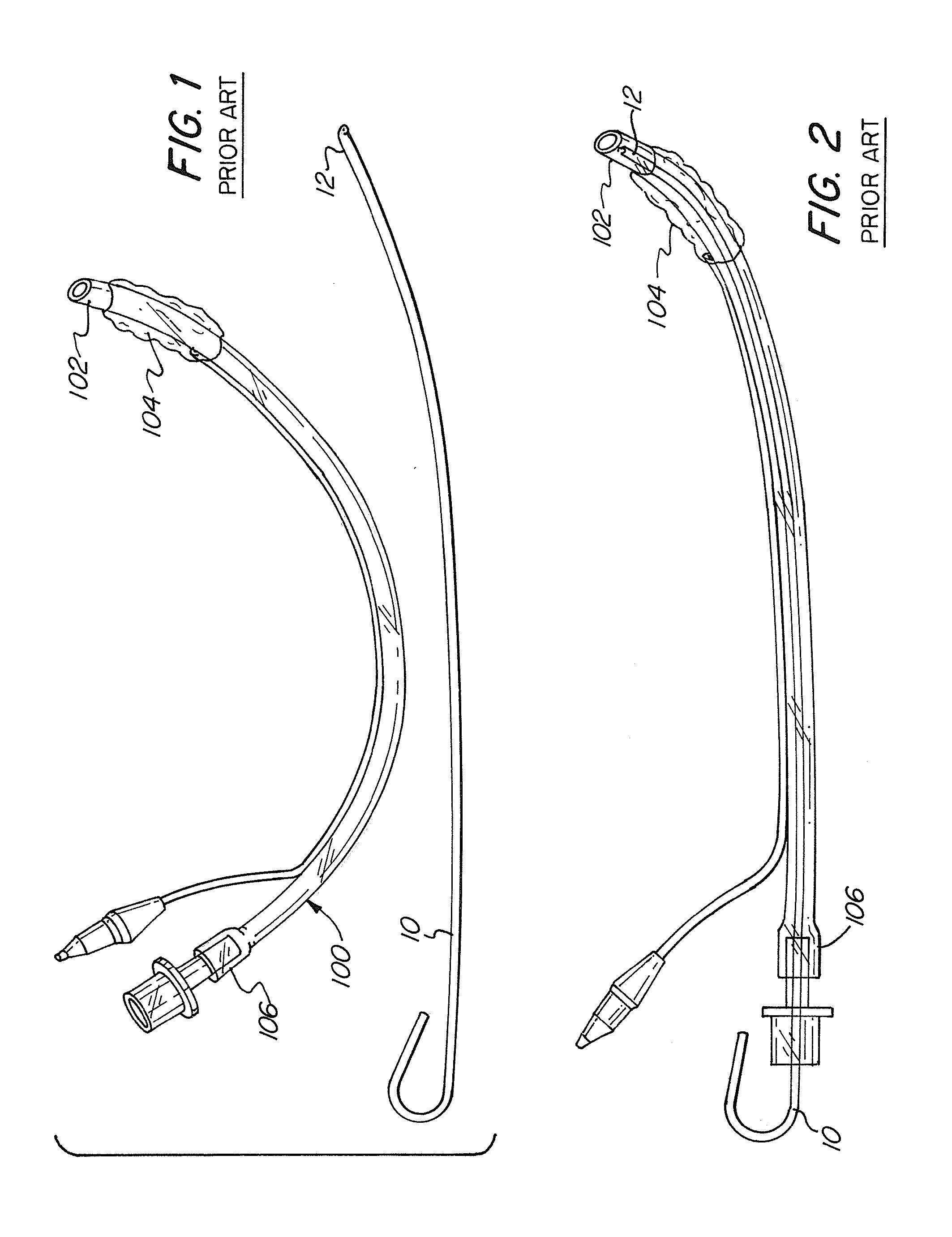
[0045]FIGS. 1 and 2 illustrate a stylet 10 and ETT 100, as is known in the prior art. As previously discussed, to intubate a patient, it is known to use a stylet 10, which is typically inserted into the ETT 100 as illustrated in FIG. 2, for introduction into the trachea. Stylet 10 typically comprises a malleable aluminum rod with a plastic cover.

[0046]The ETT typically comprises a plastic material with a distal end 102 with an inflatable cuff 104 positioned near distal end 102. Once the ETT has been inserted into the patient's trachea, the inflatable cuff 104 can be expanded to form a seal around the ETT and the inner surface of the treacha. The stylet 10 may be withdrawn and the ETT connected to a machine to facilitate breathing for the patient.

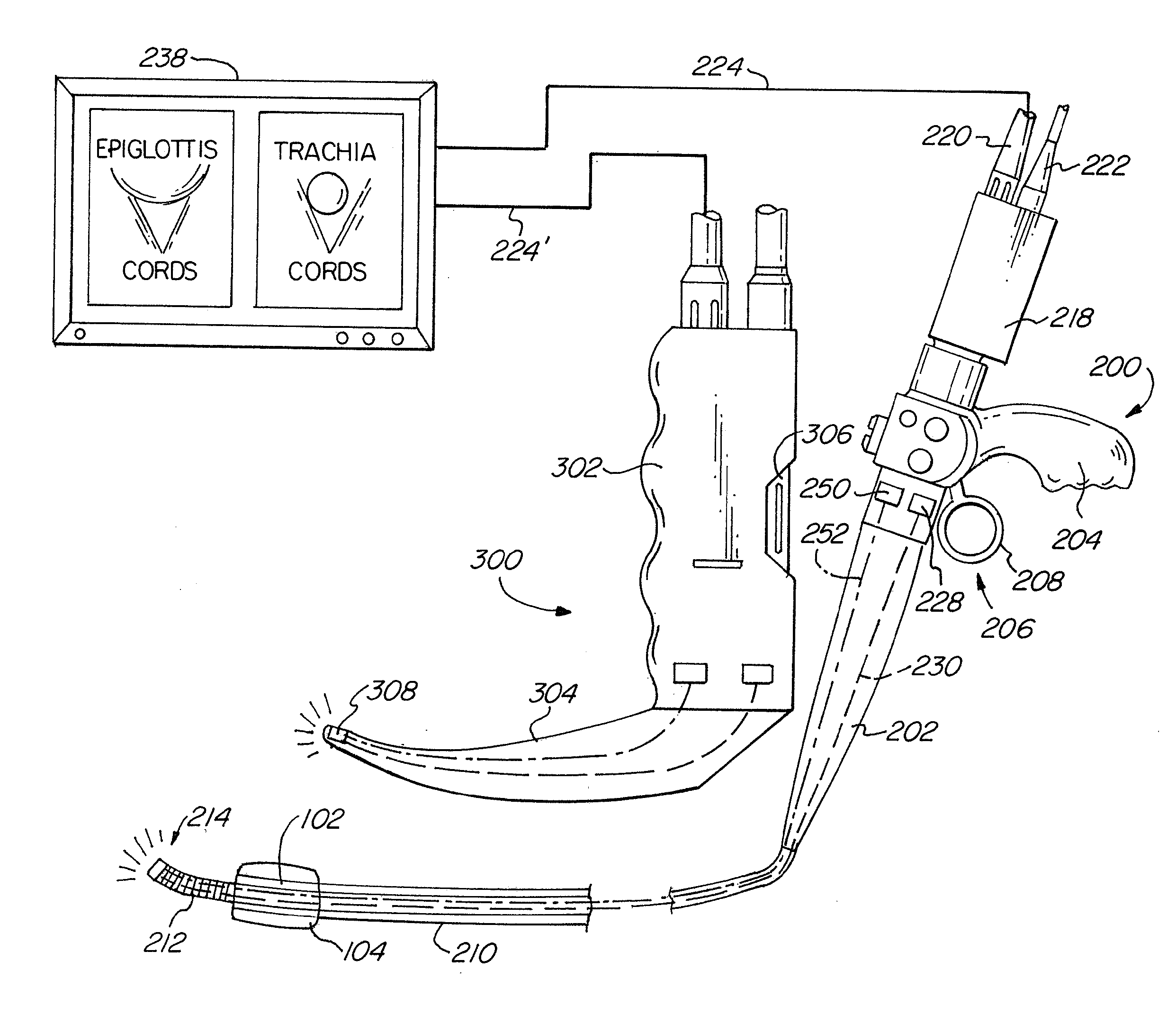
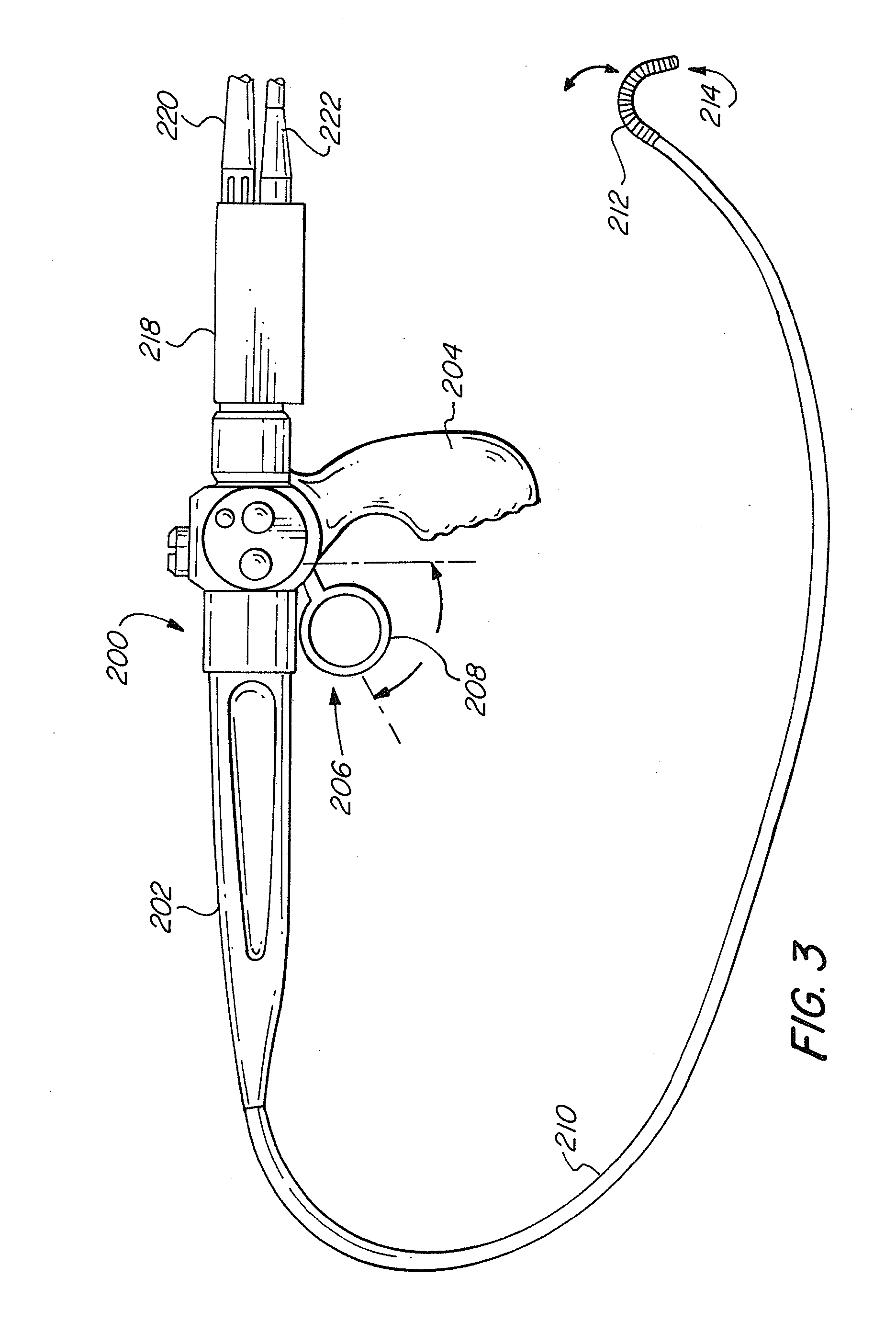
[0047]FIG. 3 is an illustration of one advantageous embodiment of the video stylet 200. The video stylet 200 includes...


PUM


Abstract

A video intubation system that provides for multiple image streams to be simultaneously presented to a user on a touch screen display, the first image stream generated by a video laryngoscope and the second image stream generated by a video stylet. The video stylet is provided with a deflection section for ease of introducing an ETT into the trachea of a patient, the video stylet having a pistol-type grip and a control interface in the form of a trigger-type lever to facilitate comfortable griping and manipulation by the user. The first and second image streams may be saved and annotated by a user as desired.

Description

FIELD OF THE INVENTION[0001]The invention relates to a video laryngoscope and video stylet that may be directed by a user, and more specifically, to a combination video laryngoscope and video stylet where the video laryngoscope and video stylet each generate a video image stream, which is displayed on a touch screen display.BACKGROUND OF THE INVENTION[0002]During a medical procedure that requires the patient to be anesthetized, the patient's breathing functions are temporarily disabled. Ventilation is supplied to the patient through an endotracheal tube. This tube is inserted into the trachea, and is typically closed against the wall of the trachea by an inflatable cuff. However, the insertion of the tube involves risks, such as, damage to the vocal cords and a prolonged intubation procedure in which the patients breathing is stopped but oxygen is not yet delivered to the patient as the tube has not yet been inserted. It is estimated that about one third of deaths occurring during a...

Claims


Application Information

Patent Timeline
Patent Type & Authority Applications(United States)
IPC IPC(8): A61B1/267A61B1/04A61B1/06
CPCA61B1/267A61B1/06A61B1/04A61B1/0005A61B1/00052A61B1/00082A61B1/0051A61B1/042A61B1/2676A61M16/0488A61M2205/587A61B1/044
Inventor BERCI, GEORGEBARRY, JAMES P.ELLIOTT, JR., JOHN J.
Owner KARL STORZ ENDOVISION INC
Why Eureka
Try Eureka