
Array substrate for liquid crystal display and manufacturing method thereof

Active Publication Date: 2013-12-05
LG DISPLAY CO LTD
View PDF3 Cites 15 Cited by
  • Summary
  • Abstract
  • Description
  • Claims
  • Application Information

AI Technical Summary

Benefits of technology

The patent aims to solve the issue of disconnection in a second metal layer and prevent defective contacts between the second metal layer and a gate pad. This is achieved by preventing the residual layer of the gate insulating layer from causing problems.

Problems solved by technology

However, in a related art array substrate for the IPS LCD, the damage of a lower layer and the inter-layer short are caused in electrically connecting the different layers through the contact holes, and particularly, the frequency of occurrence of the drawbacks is high in the gate pad area.
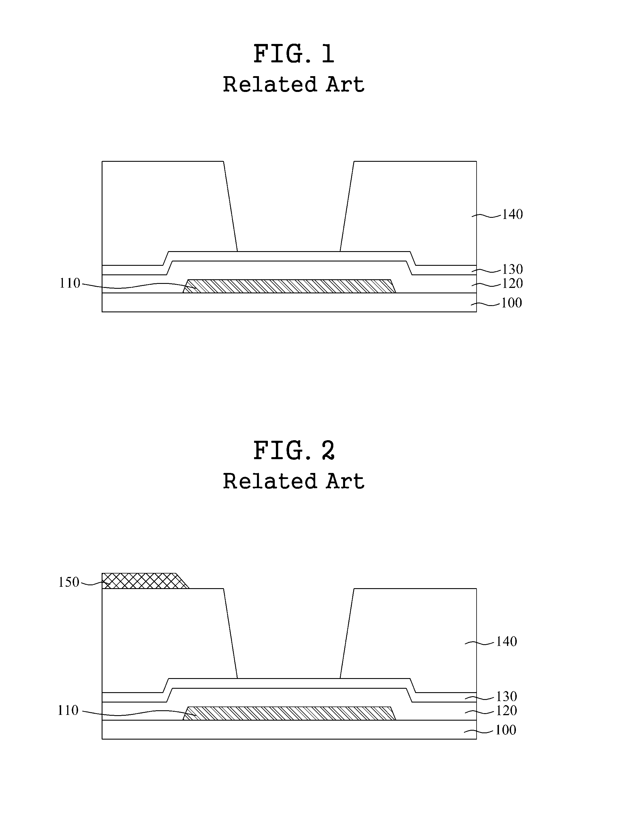
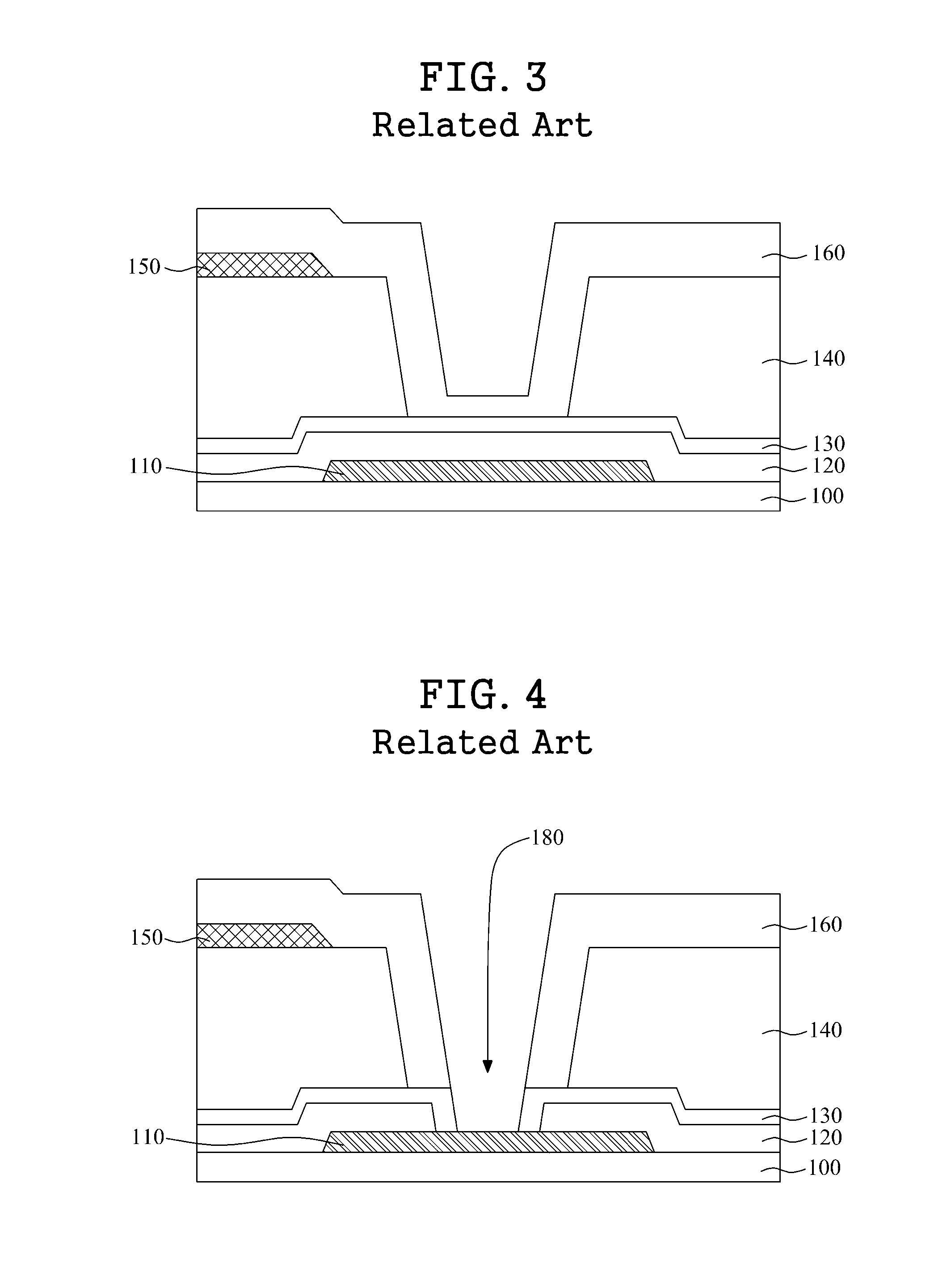
However, in the related art process of manufacturing the gate pad area of the array substrate for LCDs, some drawbacks are caused when a contact hole is deep or a step height between stacked layers is large.
First, when a step height between the gate pad and the second metal layer is large, the depth of the contact hole that is formed for electrically connecting the gate pad and the second metal layer becomes greater, and thus, the second metal layer cannot conformally be formed on the surface of the contact hole, causing the disconnection of the second metal layer.

Method used


Image

  • Array substrate for liquid crystal display and manufacturing method thereof
  • Array substrate for liquid crystal display and manufacturing method thereof
  • Array substrate for liquid crystal display and manufacturing method thereof

Examples


Embodiment Construction

[0039]Reference will now be made in detail to embodiments of the present invention, examples of which are illustrated in the accompanying drawings. In the following description, when a detailed description of well-known functions or configurations related to this document is determined to unnecessarily cloud a gist of the invention, the detailed description thereof will be omitted. The progression of processing steps and / or operations described is an example; however, the sequence of steps and / or operations is not limited to that set forth herein and may be changed as is known in the art, with the exception of steps and / or operations necessarily occurring in a certain order. Like reference numerals designate like elements throughout. Names of the respective elements used in the following explanations are selected only for convenience of writing the specification and may be thus different from those used in actual products.

[0040]In description of embodiments of the present invention,...


PUM


Abstract

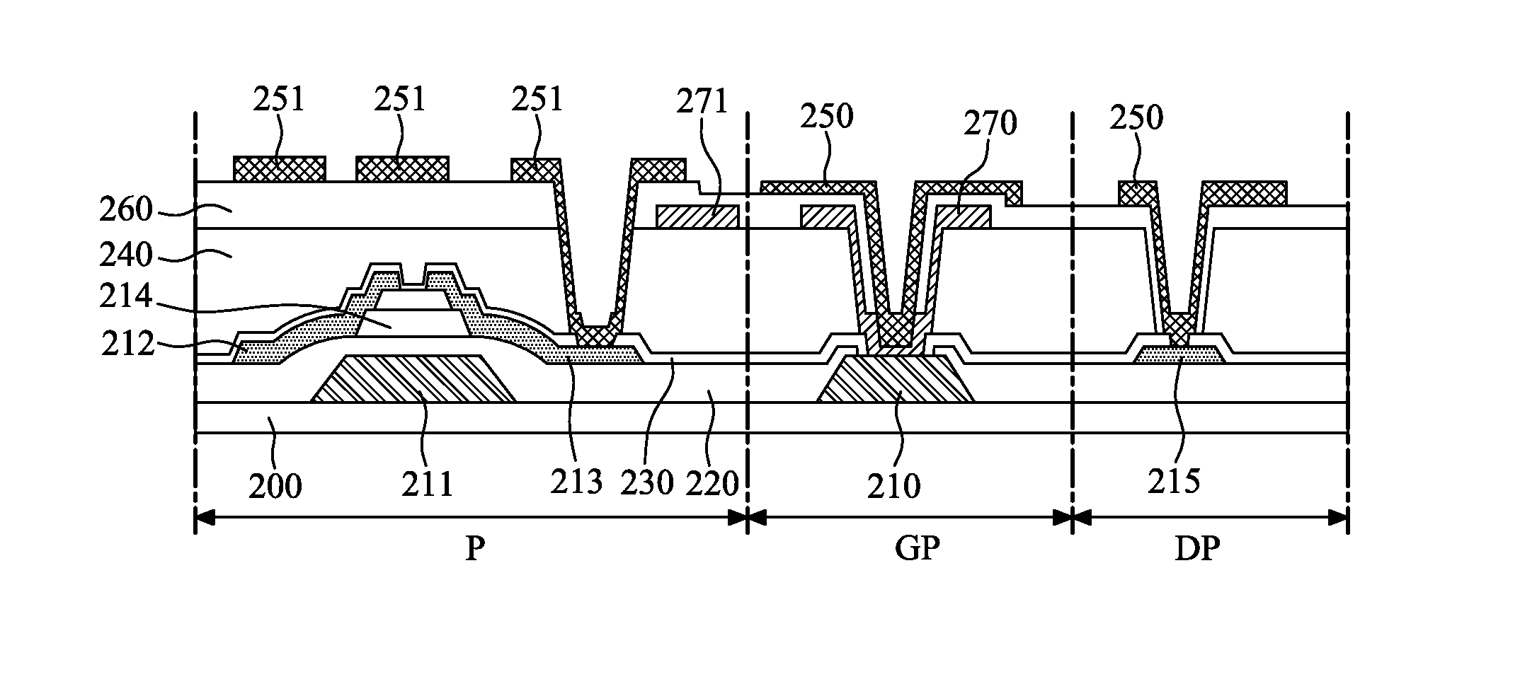
An array substrate for a liquid crystal display (LCD) and manufacturing method thereof are provided. The array substrate for a liquid crystal display (LCD) includes: a substrate, including: a gate electrode, a pixel electrode, and a common electrode, a gate pad formed on the substrate, and connected to the gate electrode, a gate insulating layer formed on the gate pad, a first protective layer formed on the gate insulating layer, a second protective layer formed on the first protective layer, a first metal layer formed on the second protective layer, and connected to the gate pad through a first contact hole which exposes the gate pad, a third protective layer formed on the first metal layer and the second protective layer, and a second metal layer formed on the third protective layer, and connected to the first metal layer through a second contact hole which exposes the first metal layer.

Description

CROSS-REFERENCE TO RELATED APPLICATION(S)[0001]This application claims the benefit under 35 U.S.C. §119(a) of Korean Patent Application No. 10-2012-0057966, filed on May 31, 2012, in the Korean Intellectual Property Office, the entire disclosure of which is incorporated by reference herein for all purposes.BACKGROUND[0002]1. Technical Field[0003]The following description relates to a liquid crystal display (LCD), and more particularly, to an array substrate for LCDs.[0004]2. Discussion of the Related Art[0005]In-plane switching (IPS) LCDs, in which a plurality of electrodes are alternately disposed at one of upper and lower substrates and liquid crystal is aligned between the substrates to thereby display an image, are being recently developed as a type of LCD.[0006]Generally, IPS LCDs adjust the light transmittance of liquid crystal having dielectric anisotropy by using an electric field and thus display an image. Here, a color filter substrate with a color filter array formed ther...

Claims


Application Information

Patent Timeline
IPC IPC(8): H01L33/36
CPCH01L33/36G02F1/13458G02F1/134372G02F1/1343G02F1/136G02F1/1368H01L27/124
Inventor WOO, YOONHWANLEE, SUNJUNG
Owner LG DISPLAY CO LTD
Learn More