
Display Panel and Drive Method of Panel Display Device

a display panel and drive method technology, applied in the field of panel display techniques, can solve the problems of non-uniform luminance distribution and affect the display result of the display panel, and achieve the effects of enhancing display equality, reducing or reducing luminance distribution

Inactive Publication Date: 2013-12-05
TCL CHINA STAR OPTOELECTRONICS TECH CO LTD
View PDF6 Cites 4 Cited by
  • Summary
  • Abstract
  • Description
  • Claims
  • Application Information

AI Technical Summary

Benefits of technology

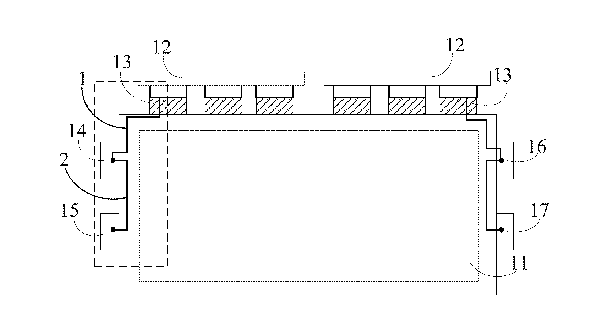
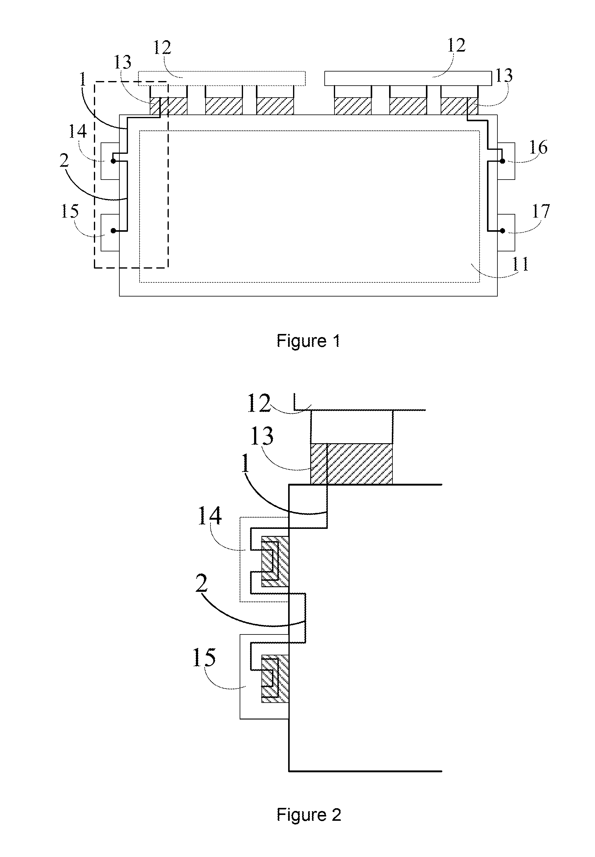
The present invention aims to improve the quality of displaying on a display panel by making the luminance distribution more uniform. To achieve this, the invention connects the input terminal of a scan signal to the output terminal of another scan signal through a wire. The resistance of the wire is balanced with at least two scan signals to ensure the amplitudes and waveforms of the signal inputs are the same. This reduces or eliminates the problem of uneven lighting on the display panel, resulting in a more uniform and high-quality display.

Problems solved by technology

The non-uniformity of luminance distribution will affect the display result of display panel.

Method used


Image

  • Display Panel and Drive Method of Panel Display Device
  • Display Panel and Drive Method of Panel Display Device
  • Display Panel and Drive Method of Panel Display Device

Examples


Embodiment Construction

[0033]The display panel of the present invention can reduce or even eliminate luminance vertical distribution phenomenon of display panel, make luminance distribution uniform and enhance displaying equality of display panel.

[0034]The following description refers to drawings and embodiments of the present invention.

[0035]Refer to FIG. 5. An embodiment of the display panel of the present invention comprises a plurality of scan lines 106, a plurality of data lines 107, a data IC 101, a first scan IC 102, a second scan IC 103 and a printed circuit board (PCB) 105. Scan lines 106 are disposed horizontally, and data lines 107 are disposed vertically. Data IC 101, first scan IC 102 and second scan IC 103 are disposed at side area 104 of display panel. In the instant embodiment, data lines 107 are disposed vertically on display panel and scan lines 106 are disposed laterally (horizontally) on display panel. Data IC 101 is disposed on a side in a direction perpendicular to data lines 107, an...


PUM


Abstract

The present invention discloses a display panel, including data IC and at least two scan ICs. Data IC includes input and output terminals of first scan signal. Scan IC includes input and output terminals of second scan signal. Input terminal of each scan IC is connected to output terminal of first scan signal on data IC through respective wire. Wires have equal resistance or have resistance difference smaller than a default value. The present invention also provides a panel display device and drive method thereof. As such, the present invention can improve luminance uniformity of display panel.

Description

BACKGROUND OF THE INVENTION[0001]1. Field of the Invention[0002]The present invention relates to the field of panel displaying techniques, and in particular to a display panel and method of panel display device.[0003]2. The Related Arts[0004]Panel display device has the advantages of flat, reduced thickness, light weight, and low power consumption so that the panel display device is replacing conventional CRT display to become the mainstream of display device. As the technologies develop, users have higher demands of panel display devices to obtain better display quality.[0005]The parameters affecting panel display device are mainly contrast, luminance, viewable angle, response time, and so on. In particular, the luminance of the display panel is an important indicator in evaluating the quality of the panel display device. Besides backlight source, the luminance of display panel also depends on routing (layout) of drive IC of display panel.[0006]Refer to FIG. 1 and FIG. 2. Panel dis...

Claims


Application Information

Patent Timeline
Patent Type & Authority Applications(United States)
IPC IPC(8): G06F3/038
CPCG02F1/1345G09G3/20G09G2300/0426G09G2320/0223
Inventor ZHENG, HUACHEN, CHENG-HUNG
Owner TCL CHINA STAR OPTOELECTRONICS TECH CO LTD
Learn More