Bearing arrangement for a reciprocating compressor

a reciprocating compressor and bearing arrangement technology, which is applied in the direction of crankshafts, piston pumps, positive displacement liquid engines, etc., can solve the problems of reducing the useful bearing area, affecting the grinding process of the shaft, and increasing the shape errors (circularity and cylindricity) of the cranksha

a reciprocating compressor and bearing arrangement technology, which is applied in the direction of crankshafts, piston pumps, positive displacement liquid engines, etc., can solve the problems of reducing the useful bearing area, affecting the grinding process of the shaft, and increasing the shape errors (circularity and cylindricity) of the cranksha

US20130323030A1Active Publication Date: 2013-12-05EMBRACO IND DE COMPRESSORES E SOLUCOES EM REFRIGERACAO LTDA

Image

  • Bearing arrangement for a reciprocating compressor
  • Bearing arrangement for a reciprocating compressor
  • Bearing arrangement for a reciprocating compressor

Examples


Embodiment Construction

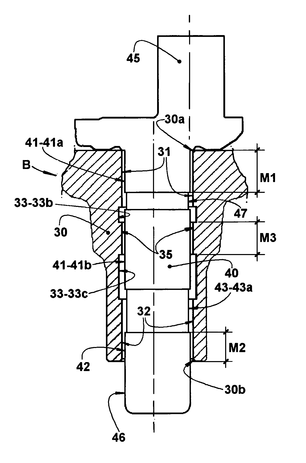
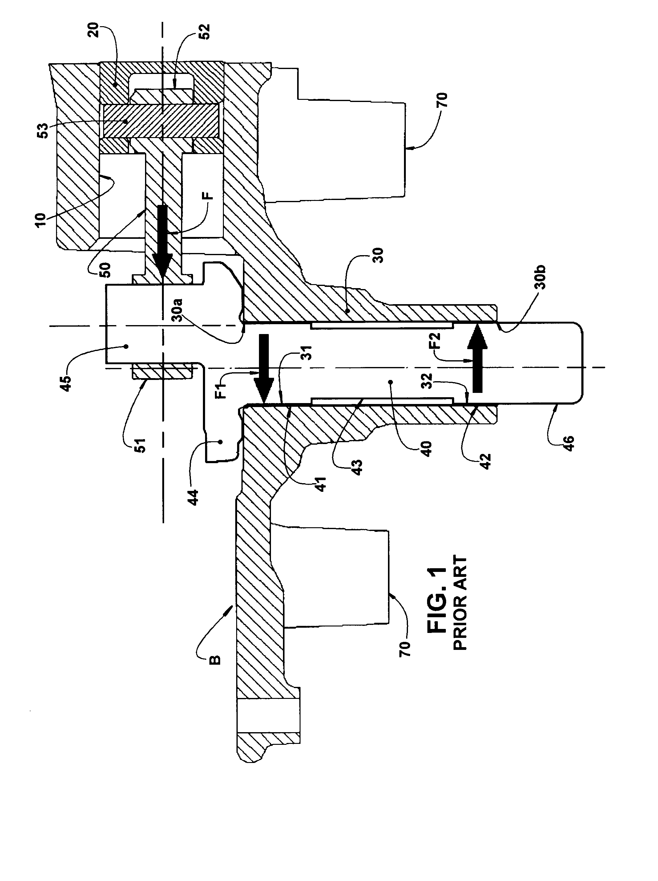
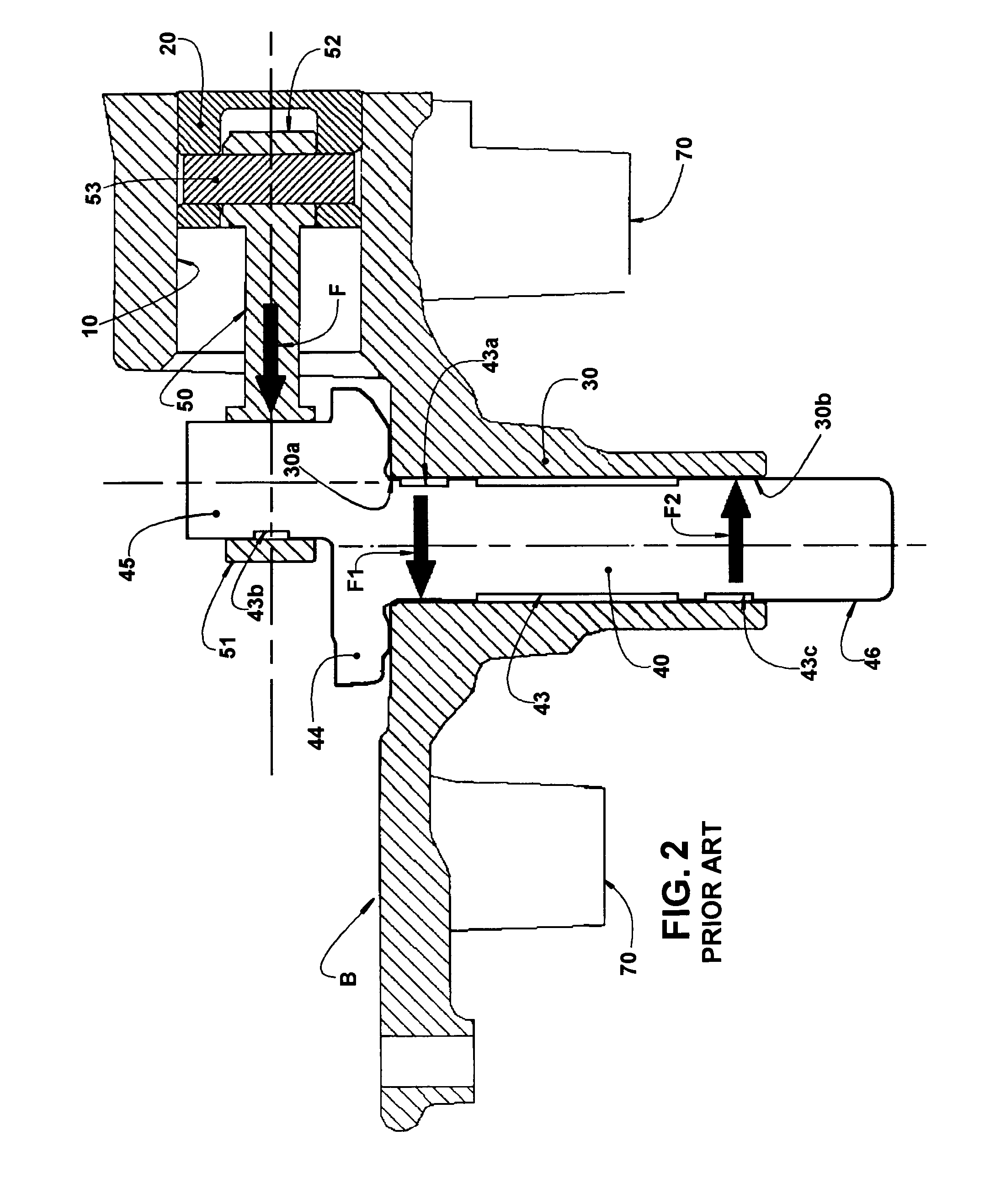
[0033]As already previously described, the bearing arrangement of the present invention is applied to a refrigeration compressor of the type partially illustrated in the enclosed drawings and which includes, in the interior of a shell (not illustrated), a crankcase B which comprises cylinder 10, at least, and one bearing hub 30 having a first end 30a and a second end 30b.

[0034]The bearing hub 30 houses a crankshaft 40 which incorporates an eccentric end portion 45, projecting axially outwards from the first end 30a of the bearing hub 30, and a free end portion 46, which projects axially outwards from the second end 30b of the bearing hub 30. Although FIGS. 4 and 5 do not illustrate the cylinder, the piston and the connecting rod, it should be understood that such parts were suppressed only by reasons of simplification of said figures, since they are already part of the type of compressor to which the present bearing arrangement is applied.

[0035]The parts of crankcase B and cranksha...


PUM


Abstract

The arrangement of the present invention is applied to a compressor which comprises a bearing hub housing a crankshaft and presenting at least a first and a second bearing portion, spaced apart by a circumferential recess. The crankshaft presents at least a first and a second support portion, spaced apart by a circumferential recess, which is offset from the circumferential recess of the bearing hub. At least one of the bearing portions and support portions has an axial extension superior to that required for radially bearing the crankshaft, the first and second bearing portions defining, with the first and second support portions, respectively, a first and a second radial bearing regions having the axial extensions required for a radial bearing for the crankshaft, presenting lower loss by viscous friction.

Description

FIELD OF THE INVENTION[0001]The present invention refers to a constructive arrangement for providing a radial bearing for the crankshaft of a reciprocating refrigeration compressor, either hermetic or not, presenting smaller viscous friction losses in relation to the known bearing arrangements.PRIOR ART[0002]The refrigeration compressors of the reciprocating type, generally have a mechanical assembly composed by a crankcase, a crankshaft, at least one connecting rod and at least one piston, which elements are arranged so that the rotating movement of the crankshaft, provided by an electric motor of the compressor, is converted to a reciprocating linear movement of the piston.[0003]A conventional construction of a reciprocating compressor, of the type illustrated in FIG. 1, presents, in the interior of a shell (not illustrated), a crankcase B which defines a cylinder 10, inside which reciprocates a piston 20.[0004]The crankcase B is also provided with a bearing hub 30, whose inner su...

Claims


Application Information

Patent Timeline
05 Dec 2013
Publication
US20130323030A1
IPC
F01D25/16
CPC
F01D25/16; F04B39/0094; F16C3/14; F16C3/18; F16C3/22; F16C9/02; F16C33/106; F04B39/00
Inventors
MANKE, ADILSON LUIZ