Electric cells and assembled battery

Inactive Publication Date: 2013-12-05
HITACHI AUTOMOTIVE SYST LTD
View PDF6 Cites 21 Cited by
  • Summary
  • Abstract
  • Description
  • Claims
  • Application Information

AI Technical Summary

Problems solved by technology

While the secondary cell of JP-2011-233399-A allows connection of busbars to external terminals by nuts and bolts, it does not allow welding of the busbars to the external t

Method used


Image

  • Electric cells and assembled battery
  • Electric cells and assembled battery
  • Electric cells and assembled battery

Examples


Embodiment Construction

[0026]With reference to the accompanying drawings, an assembled battery according to an embodiment of the invention will now be described. The battery is intended for use for the electric storage devices of electric cars, whether hybrid or regular, and includes multiple rectangular lithium-ion secondary cells (hereinafter referred to as ‘electric cells’ or simply as ‘cells’).

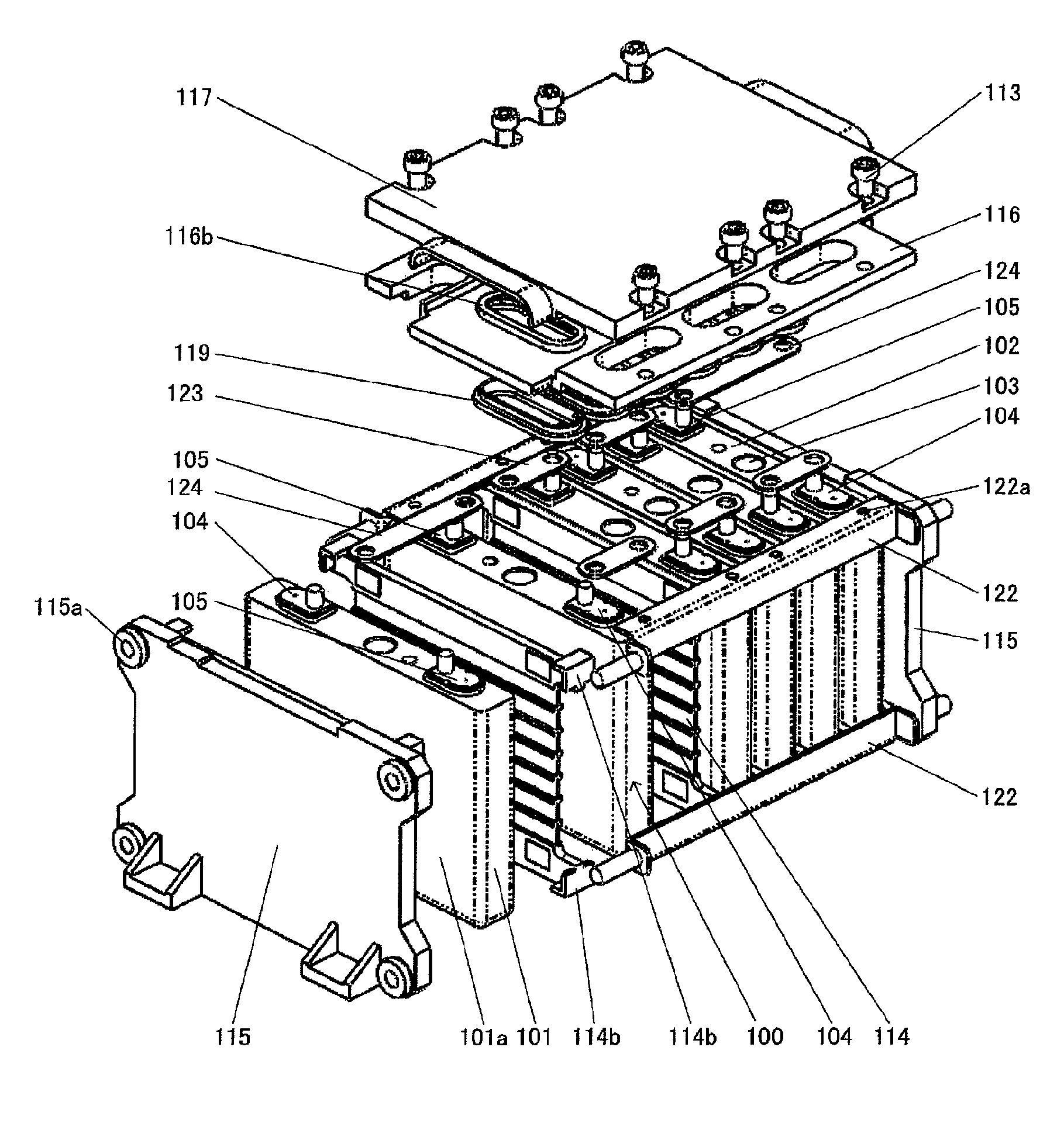
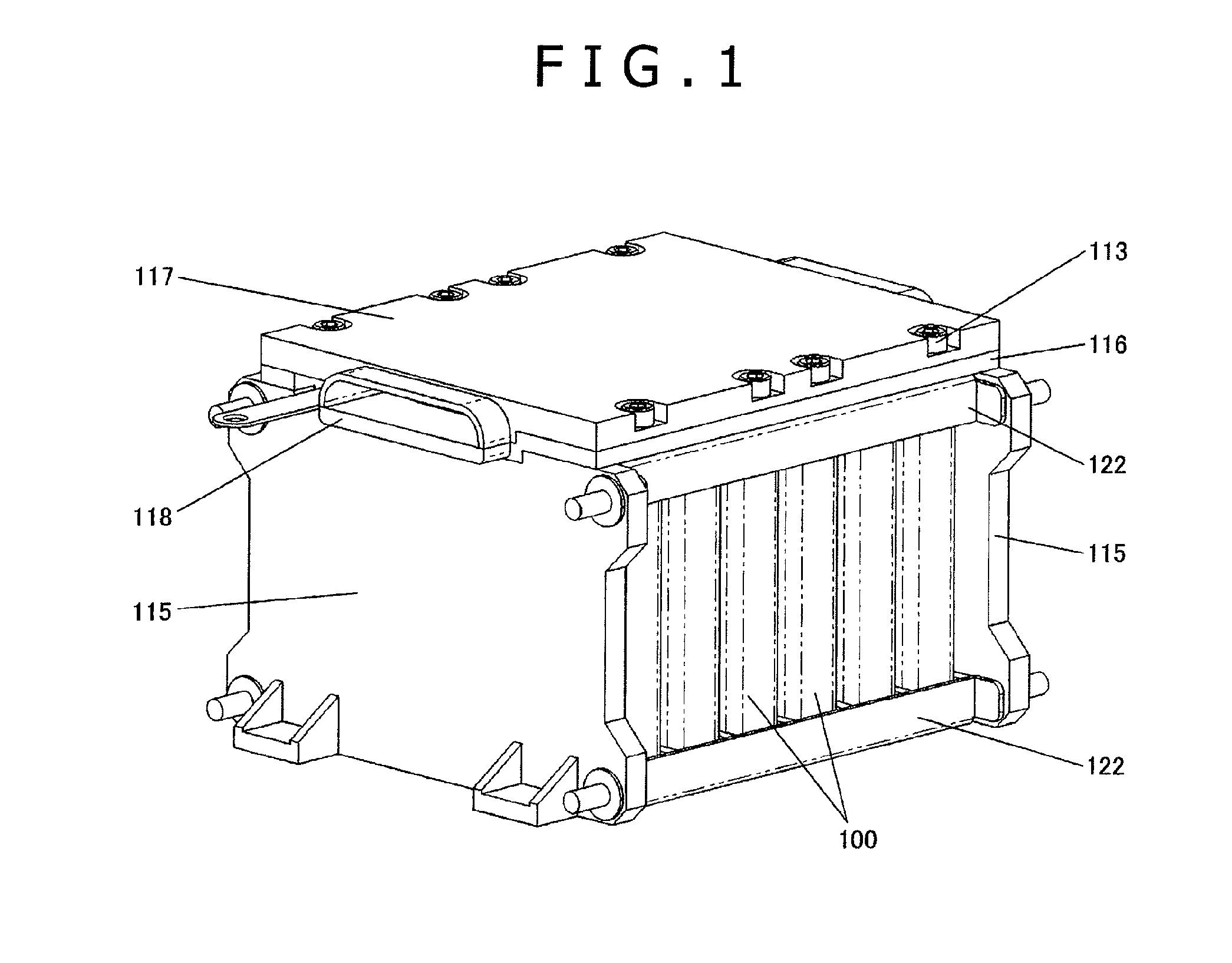
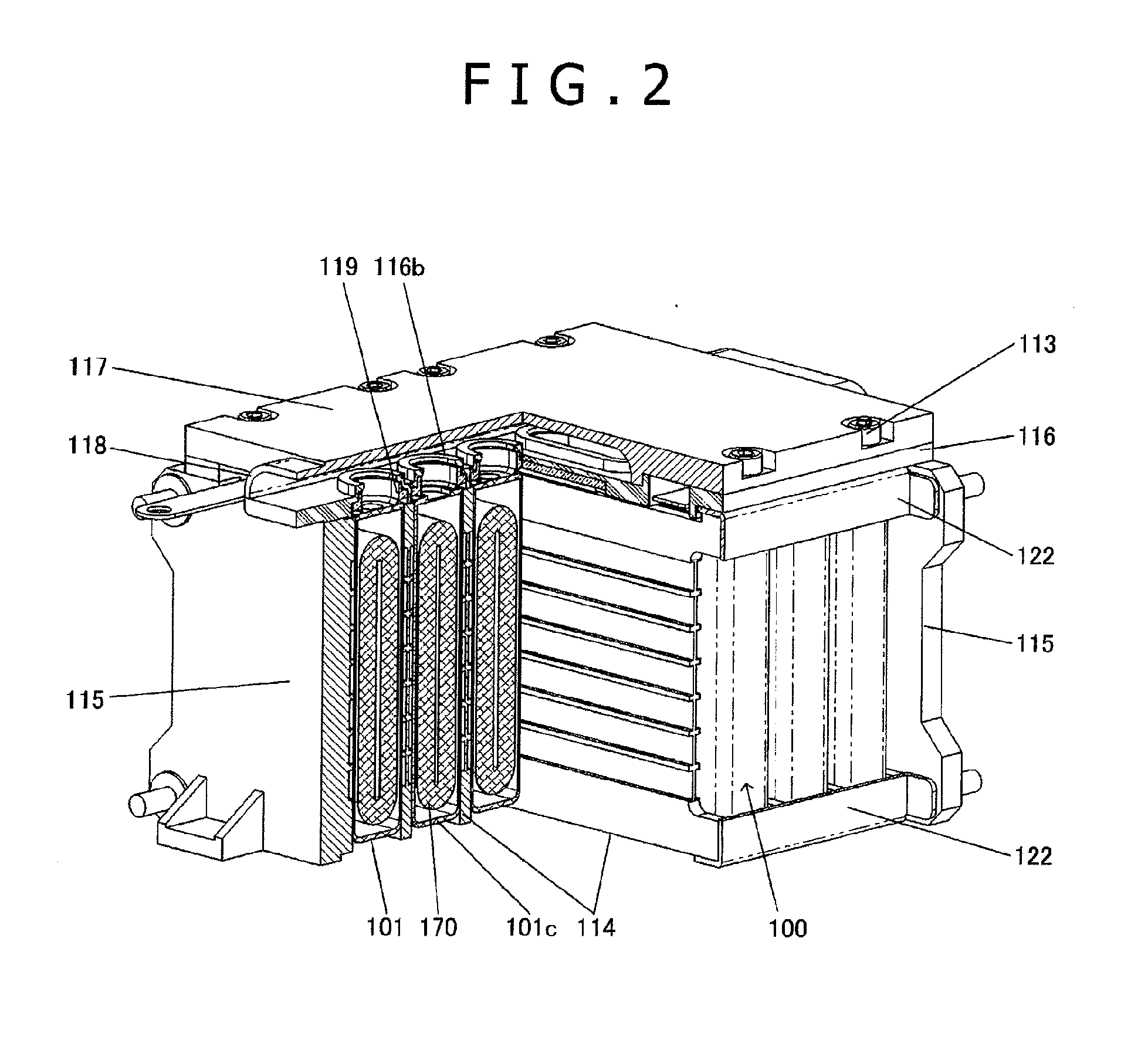
[0027]FIGS. 1, 2, and 3 are an external perspective view, cross-sectional perspective view, and exploded perspective view, respectively, of the assembled battery. The battery includes multiple electric cells 100. The electric cells 100 are arranged side by side and assembled into a single unit by a pair of end plates 115, multiple cell holders 114, and four shafts 122. The electric cells 100 arranged are sandwiched by the end plates 115 from the both ends of the arrangement direction (i.e., a longitudinal direction of the battery). The electric cells 100 are protected from above by a top plate 116 and a top cove...


PUM


Abstract

An electric cell comprises: a power generating element including electrodes; a cell container including a cell case for housing the power generating element and a cell cover for sealing an opening of the cell case; two external terminals disposed on the cell cover; and two collector electrodes for connecting the electrodes of the power generating element to the external terminals; wherein each of the external terminals includes: a connector connected to one of the collector electrodes within the cell container; a flat section located right above the connector and exposed to the outside of the cell container; and a bolting section located adjacent to the flat section and having an insertion hole, and wherein the connector, the flat section, and the bolting section are integrally formed. The electric cell allows connection of external terminals to busbars either by bolting or welding.

Description

BACKGROUND OF THE INVENTION[0001]1. Field of the Invention[0002]The present invention relates to electric cells and an assembled battery including multiple electric cells.[0003]2. Description of the Related Art[0004]Secondary cells with high capacity (Wh) are now being developed as the power sources of hybrid or regular electric automobiles. Among them, rectangular lithium-ion secondary cells are receiving the most attention because they are high in energy density (Wh / kg).[0005]Rectangular lithium-ion secondary cells each use a flat wound-electrode assembly. To fabricate the wound-electrode assembly, a positive foil is coated with a positive active material to form a positive electrode, and a negative foil is coated with a negative active material to form a negative electrode. These positive and negative electrodes are then wound with insulating separators placed between them. The resultant wound-electrode assembly is electrically connected to the positive and negative external term...

Claims


Application Information

Patent Timeline
IPC IPC(8): H01M2/20H01M50/176H01M50/516H01M50/517H01M50/55H01M50/553H01M50/567
CPCH01M2/206H01R4/06H01M10/052H01R11/283Y02E60/10H01M50/516H01M50/567H01M50/517H01M50/55H01M50/553H01M50/176
Inventor TSUNAKI, TAKUROSASAKI, TAKASHIURANO, KAZUAKISAIMARU, SHO
Owner HITACHI AUTOMOTIVE SYST LTD
Why Eureka
Try Eureka