
Belt-driven continuously variable transmission

a continuously variable transmission and belt drive technology, applied in the direction of gearing control, gearing elements, gearing rings, etc., can solve the problems of enlarge the size of the belt-driven continuously variable transmission, and achieve the effect of preventing slippage of the driving belt, fixing the speed ratio, and not waste of energy

Inactive Publication Date: 2013-12-05
TOYOTA JIDOSHA KK
View PDF42 Cites 3 Cited by
  • Summary
  • Abstract
  • Description
  • Claims
  • Application Information

AI Technical Summary

Benefits of technology

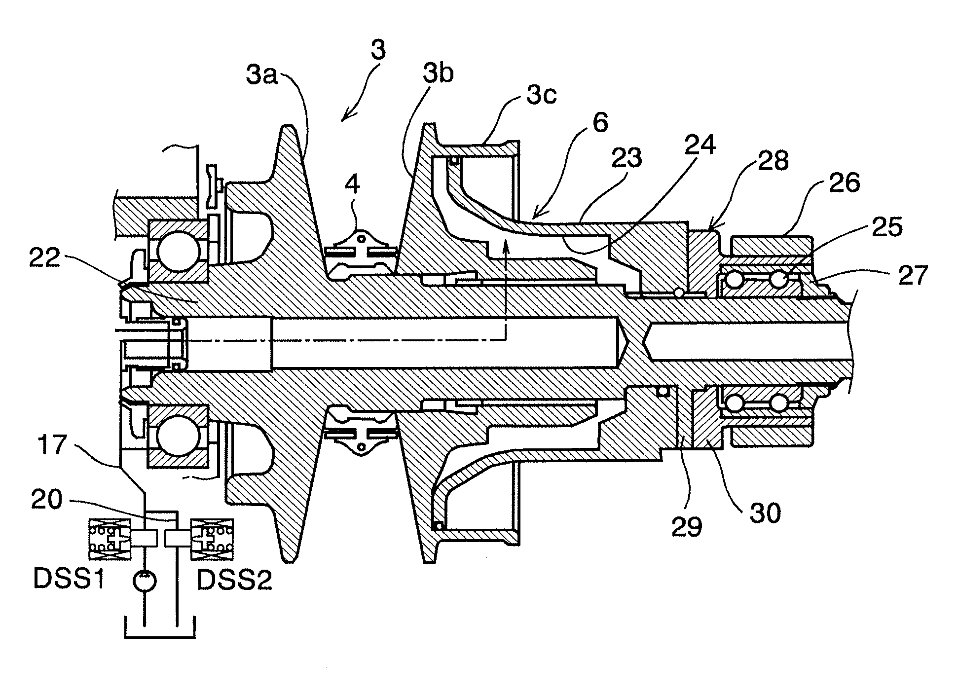
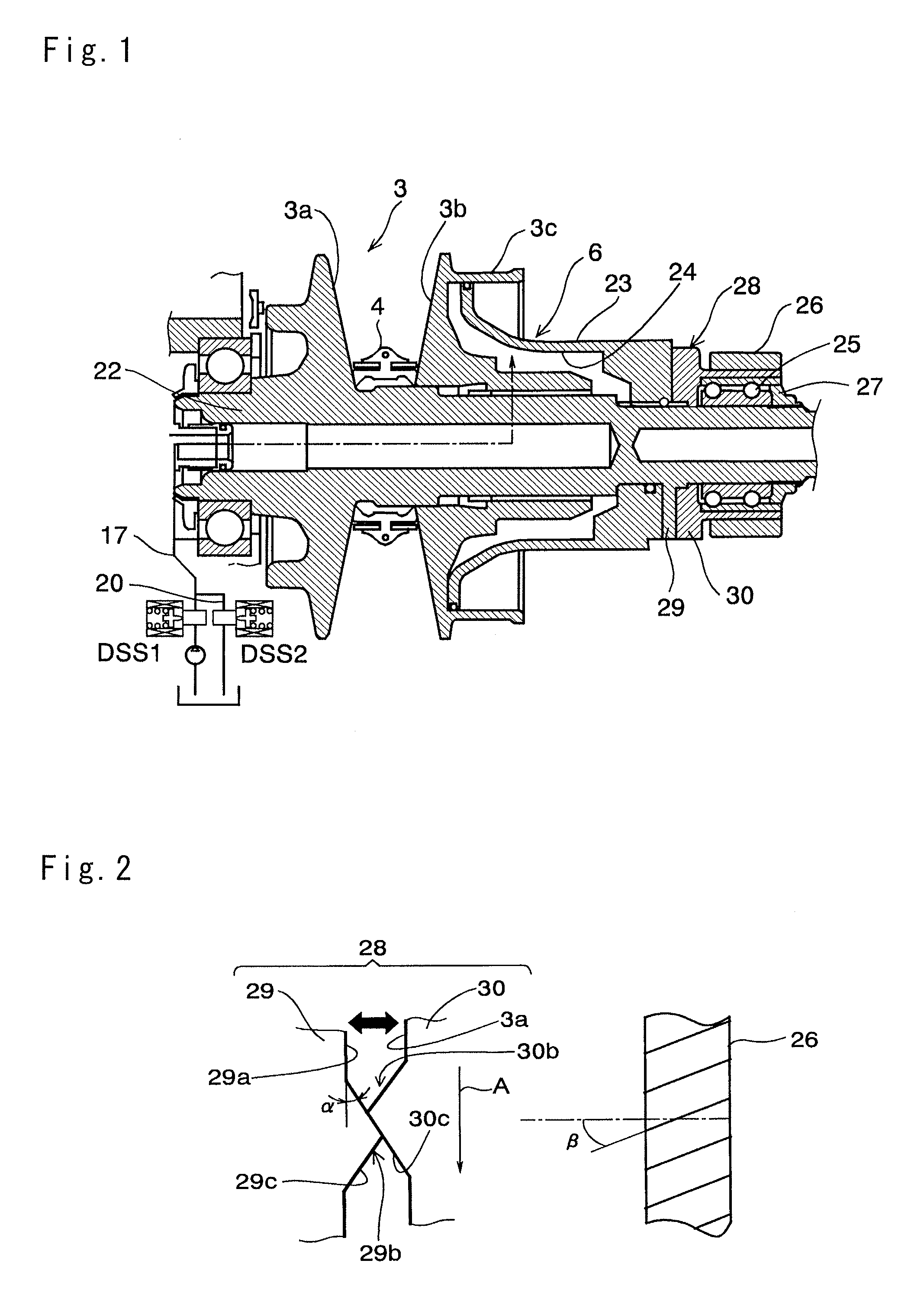
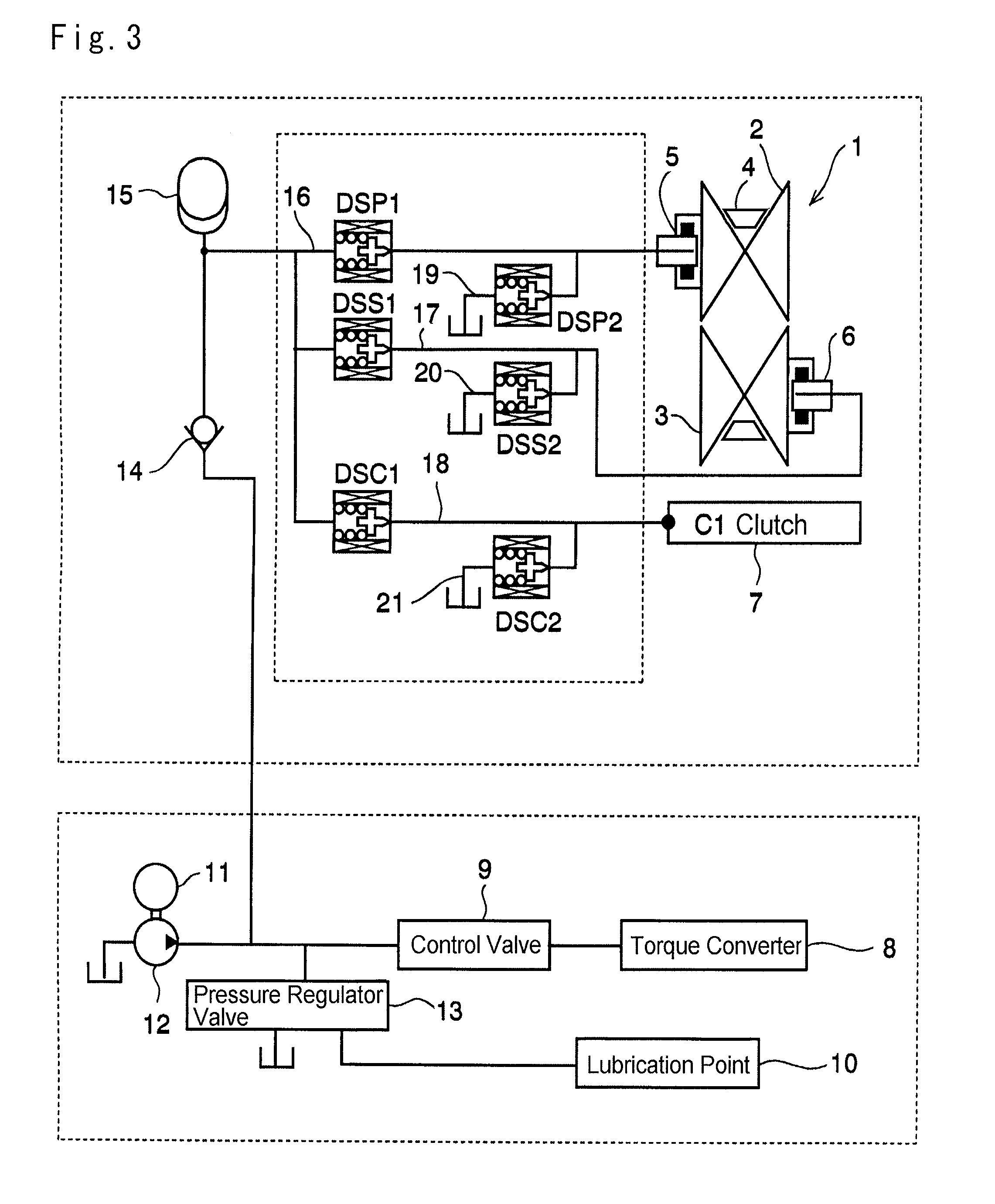
The present invention is about a new type of belt-driven continuously variable transmission (CVT) for vehicles. The invention includes a torque cam assembly that works with a piston to increase the pressure in the hydraulic chamber, ensuring the required clamping pressure for transmitting torque. This helps to prevent belt slippage and improves the quality and lifespan of the transmission. The torque cam assembly is also smaller in size, making it easier to mount on vehicles. The invention also fixes the speed ratio by confining the hydraulic pressure in the chambers, eliminating the need for constant pressure regulation and improving fuel economy.

Problems solved by technology

Therefore, the torque cam mechanism of this kind has to be large enough to push the movable sheave certainly, and this may enlarge a size of the belt-driven continuously variable transmission.

Method used


Image

  • Belt-driven continuously variable transmission
  • Belt-driven continuously variable transmission
  • Belt-driven continuously variable transmission

Examples


Embodiment Construction

[0018]Next, the present invention will be explained in more detail. The belt-driven continuously variable transmission of the present invention is comprised of a driving pulley, a driven pulley of an output side, and a driving belt applied to those pulleys. Accordingly, a speed ratio in the belt-driven continuously variable transmission is changed by displacing an effective diameter position of the driving belt continuously. Specifically, the effective diameter position of the driving belt is displaced by changing a width of V-shaped groove (as will be called a belt groove hereinafter) of each pulley. Each pulley is individually comprised of a pair of sheaves, and a conical surface is formed on an inner face of each sheave to be opposed to each other. One of those sheaves is integrated with a rotary shaft (as will be called a fixed sheave hereinafter), and the other sheave is allowed to reciprocate with respect to the fixed sheave (as will be called a movable sheave hereinafter). Ac...


PUM


Abstract

A belt-driven continuously variable transmission having a downsized torque cam assembly for creating forward thrust to push a movable sheave toward a fixed sheave.The belt-driven continuously variable transmission is adapted to output a torque while changing a speed ratio continuously by altering an effective diameter position of a driving belt. The belt-driven continuously variable transmission is comprised of: an output gear, which is fitted onto the rotary shaft of the driven pulley to output the torque while being allowed to rotate relatively; a piston, which is fitted onto the rotary shaft of the driven pulley between the movable sheave and the output gear while being allowed to rotate integrally with the movable sheave and to reciprocate in an axial direction of the rotary shaft, and which increases an internal pressure of the hydraulic chamber by moving toward the movable sheave; and a torque cam assembly, which is interposed between the piston and the output gear, and which pushes the piston toward the movable sheave when the torque transmitted through the driven pulley is increased.

Description

TECHNICAL FIELD[0001]This invention relates to a belt-driven continuously variable transmission adapted to change a speed ratio continuously by varying an effective diameter position of a driving belt.BACKGROUND ART[0002]The belt-driven continuously variable transmission is adapted to change a speed ratio continuously by varying a groove width of a pulley holding a driving belt therebetween to displace an effective diameter position of the driving belt. A primary pulley and a secondary pulley of the transmission are individually comprised of a fixed sheave and a movable sheave. A speed ratio in the belt-driven continuously variable transmission thus structured is changed continuously by displacing an effective diameter position of the driving belt by hydraulically reciprocating the movable sheave to vary a groove width of the pulley. Specifically, a main role of the primary pulley is to control the speed ratio. For this purpose, the primary pulley is provided with a primary hydrauli...

Claims


Application Information

Patent Timeline
Patent Type & Authority Applications(United States)
IPC IPC(8): F16H9/16
CPCF16H9/16F16H55/56F16H61/66272F16H63/065
Inventor KAWAKAMI, TAKAHOYANAGIDA, TOMOAKIMORIYAMA, SHUJIMORINO, TAKURO
Owner TOYOTA JIDOSHA KK
Learn More