Roadheader gearbox

a gearbox and roadheader technology, applied in the field of gearboxes, can solve problems such as damage and premature wear

Inactive Publication Date: 2013-12-05
FAIRFIELD MFG CO INC
View PDF13 Cites 35 Cited by
  • Summary
  • Abstract
  • Description
  • Claims
  • Application Information

AI Technical Summary

Problems solved by technology

External forces not generated by the gear system move the gears out of this alignment and thus adversely affect the gear position causing damage and premature wear.

Method used


Image

  • Roadheader gearbox
  • Roadheader gearbox
  • Roadheader gearbox

Examples


Embodiment Construction

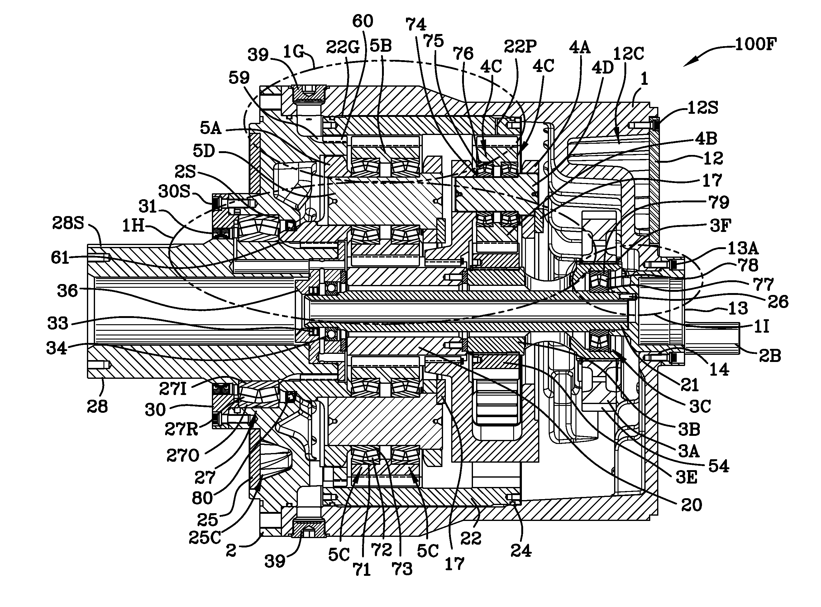
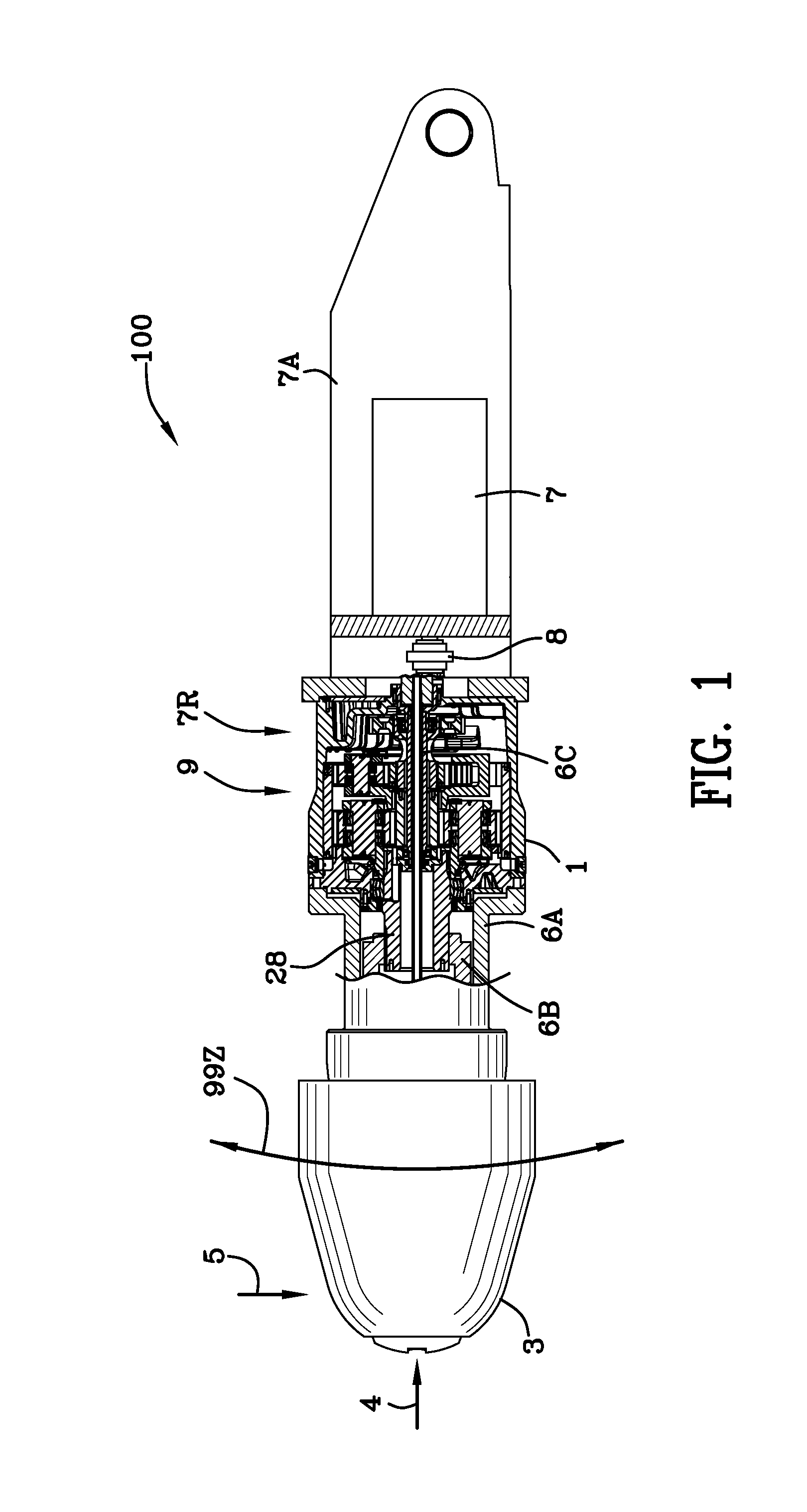
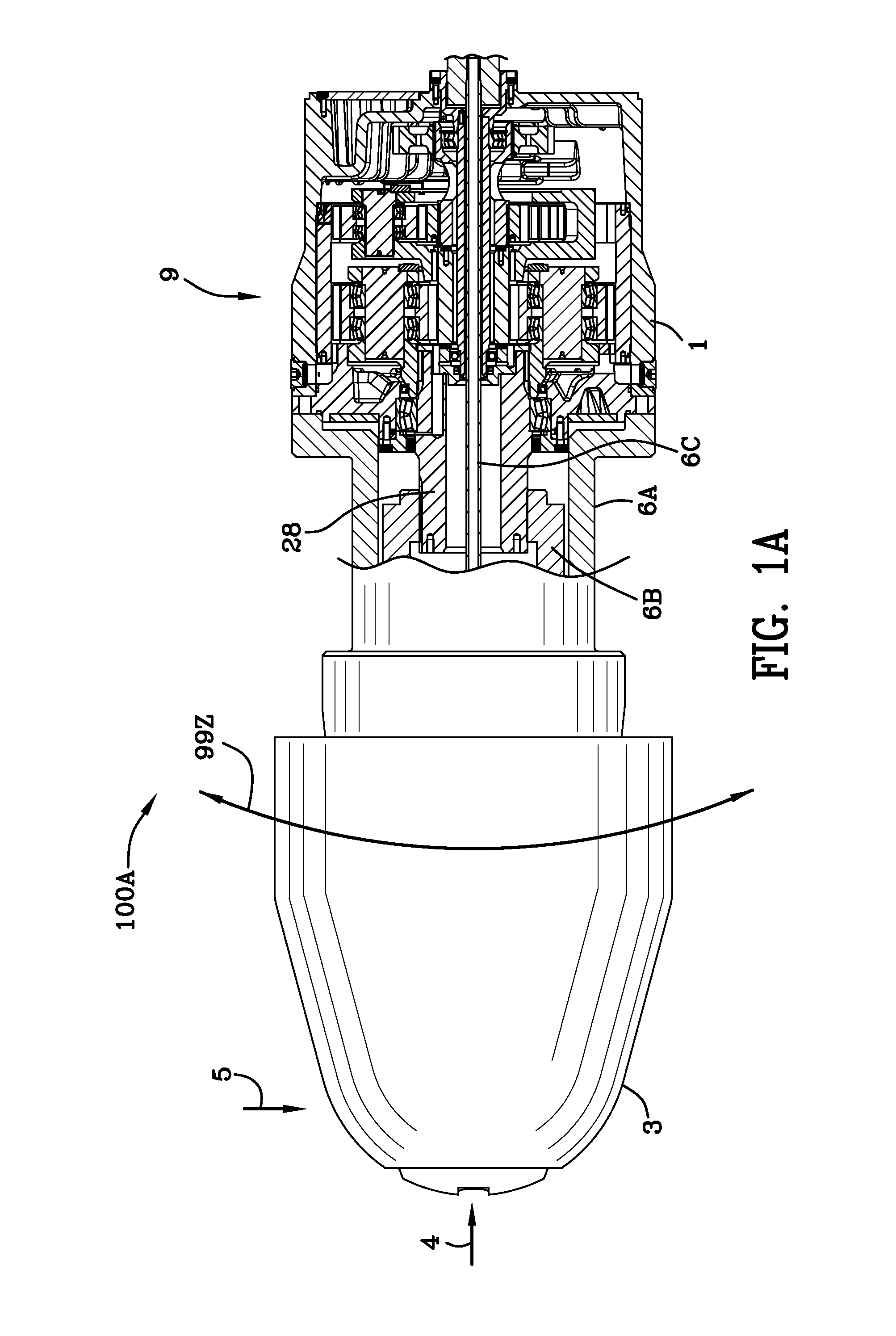
[0064]FIG. 1 is a schematic view 100 of a roadheader 7R including the cutter head 3, gearbox 9 and prime mover 7. FIG. 1A is an enlarged portion 100A of the schematic view of FIG. 1 illustrating the cutter head 3 and gearbox 9 in more detail. As illustrated in FIGS. 1 and 1A, electric motors 7 drive input gears 2B which in turn drive, via spline connections, input gears 2A. Input gears 2A drive intermediate gear 3A.

[0065]Still referring to FIGS. 1 and 1A, a horizontal or axial force 4 is imparted on the cutter head 3 in earth boring operations. The roadheader (earth boring machine) is forced into earthen material which may be very hard. The cutter head 3 includes spikes thereon (not shown) which forcibly cut into the earthen material. All of the axial forces 4 are transmitted through the frame of the cutter head 3, the coupling frame 6A, the housing 1 of the gearbox 9, the cover 2 of the gearbox 9, and the motor frame 7A. Similarly, the cutter head is subject to radial force 5 as il...


PUM


Abstract

A gearbox includes a shaft input spherical bearing and a shaft output spherical bearing enabling the ring gear to float within the housing and not engage the housing. The shaft output spherical bearing permits angular displacement of the output shaft with respect to the longitudinal axis of said output shaft. A spline connection enables the ring gear to pivot with respect to the cover. Loads transmitted to the housing of the gearbox are not transferred to the gear systems and the gear systems self-align within the housing.

Description

FIELD OF THE INVENTION [0001]The invention is in the field of gearboxes used to drive earth boring machines.BACKGROUND OF THE INVENTION[0002]A roadheader is an earth-boring machine which experiences high axial and radial loads on and in the frame of the machine. The roadheader includes a cutter head, a gearbox and a motor (prime mover). When the gearing, most notably the ring gear, is affixed to the housing of the gearbox, the axial and radial forces imparted on the cutter head are transmitted to the ring gear through the housing and cause misalignment of the gears and other components. The misalignment causes abnormal gear wear and ultimately destruction of the gears, carriers and other components.[0003]Roadheaders operate in a range of motion with respect to horizontal. In other words, the cutter head of the roadheader and the gearbox affixed thereto may be inclined with respect to horizontal and creating lubrication problems with some of the bearings within the gearbox as the bea...

Claims


Application Information

Patent Timeline
Patent Type & Authority Applications(United States)
IPC IPC(8): F16H1/46
CPCF16H1/2818F16H1/46F16H2057/02078
Inventor PHEBUS, DAN E.CARLTON, KENNETH E.
Owner FAIRFIELD MFG CO INC
Why Eureka
Try Eureka