
Industrial Methods for Producing Arylsulfur Pentafluorides

a technology of arylsulfur pentafluoride and industrial methods, which is applied in the preparation of organic compounds, antineoplastic agents, organic chemistry, etc., can solve the problems of low yield, time and/or yield, and high cost, and achieve the effects of low yield, low cost, and high cos

Inactive Publication Date: 2013-12-05
UBE IND LTD
View PDF2 Cites 4 Cited by
  • Summary
  • Abstract
  • Description
  • Claims
  • Application Information

AI Technical Summary

Benefits of technology

The patent text describes various features and advantages of a new invention. The "technical effects" of this invention will be revealed through a reading of the detailed description and review of the appended claims.

Problems solved by technology

Each of the above synthetic methods has one or more drawbacks making it either impractical (time and / or yield), overly expensive, and / or overly dangerous to practice.
For example, synthetic methods (1) and (4) provide low yields and require expensive reaction agents, e.g., AgF2 and XeF2.
Note that handling of these gasses is expensive from the standpoint of production, storage and use.
In addition, synthetic methods that require the use of F2, CF3OF, and / or CF2(OF)2 are limited to the production of deactivated arylsulfur pentafluorides, such as nitrophenylsulfur pentafluorides, due to their extreme reactivity, which leads to side-reactions such as fluorination of the aromatic rings when not deactivated.
Methods (5) and (6) also require expensive reactants, e.g., SF5Cl or SF5Br, and have narrow application because the starting cyclohexene derivatives have limited availability.
Finally, method (7) requires an expensive reactant, SF5Cl, and this method includes numerous steps to reach the arylsulfur pentafluorides (timely and low yield).
As discussed above, conventional synthetic methodologies for the production of arylsulfur pentafluorides have proven difficult and are a concern within the art.
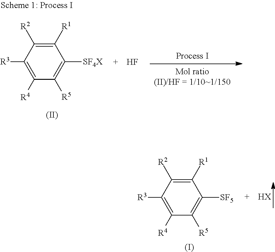
However, methods using hydrogen fluoride still have several drawbacks, including: (1) as hydrogen fluoride is severely toxic, the amount of hydrogen fluoride used for a reaction must be minimized for safety and for the sake of the environment; (2) there is evolution of a large amount of a gaseous, toxic, corrosive hydrogen halide such as HCl (bp of HCl, −85° C.) from the reaction of an arylsulfur halotetrafluoride and hydrogen fluoride; (3) in some cases, a low yield or less purity of the product is obtained, because byproducts such as chlorinated arylsulfur pentafluorides are formed by side-reactions.
These drawbacks cause significant cost problems in the industrial production of arylsulfur pentafluorides.

Method used


Image

  • Industrial Methods for Producing Arylsulfur Pentafluorides
  • Industrial Methods for Producing Arylsulfur Pentafluorides
  • Industrial Methods for Producing Arylsulfur Pentafluorides

Examples


example 1

Synthesis of Phenylsulfur Pentafluoride by Reaction of Phenylsulfur Chlorotetrafluoride with Anhydrous Hydrogen Fluoride

[0085]

[0086]While N2 gas was flowed through a 250 mL fluoropolymer (FEP) vessel set with a condenser (made of fluoropolymer), the vessel was cooled in a bath of −11° C. A coolant (−25° C.) was flowed through the condenser. The vessel cooled at −11° C. was charged with 72.3 g (3.62 mol) of anhydrous hydrogen fluoride which was cooled at −20° C. Into the vessel, 35.0 g (0.152 mol) of phenylsulfur chlorotetrafluoride (this purity was 96 wt % and the other 4 wt % was phenylsulfur trifluoride) was added over 90 min through a syringe using a syringe pump. The molar ratio of phenylsulfur chlorotetrafluoride and hydrogen fluoride was 1 / 24. After the addition, the reaction mixture was stirred at −10° C. for 20 hours. After that, the reaction mixture was warmed to 25° C. and hydrogen fluoride was removed at the temperature under atmospheric pressure. The residue was mixed wi...

example 12

Synthesis of Phenylsulfur Pentafluoride by Reaction of Phenylsulfur Chlorotetrafluoride with Anhydrous Hydrogen Fluoride in the Presence of K+F−.HF Added as an Additive

[0089]

[0090]A dried 125 mL fluoropolymer (FEP) vessel was flowed with N2 gas and charged with 48.0 g (2.40 mmol) of liquid anhydrous hydrogen fluoride which was cooled at −20° C. The vessel was set with a condenser (made of fluoropolymer) and a thermometer, and cooled in a bath of −20° C. A coolant (−15° C.) was flowed through the condenser. Into the vessel, 8.6 g (0.11 mol) of KF.HF was added. While the mixture was warmed to +15° C., 22.1 g (96.2 mmol) (purity 96 wt % and the other was phenylsulfur trifluoride) of phenylsulfur chlorotetrafluoride was added to the mixture over 1 hour through a syringe. The temperature of the reaction mixture was 3.4° C. and 13.6° C. at the starting point and completing point of the addition, respectively. After the addition, the reaction mixture was stirred at 15° C. for 18 h. After t...

example 20

Synthesis of Arylsulfur Pentafluoride (I) by Reaction of Arylsulfur Halotetrafluoride (II) with anhydrous hydrogen fluoride in the presence of a non-fluoride salt

[0095]

[0096]Liquid anhydrous hydrogen fluoride (61 g, 3.05 mol) was put in a dried 125 mL fluoropolymer vessel in the same way as in Example 12. The vessel was then set with a condenser (made of fluoropolymer) and a thermometer, and cooled in a bath of −20° C. Sodium acetate (9.0 g, 0.11 mol) was added portion by portion into a stirred liquid of hydrogen fluoride in the vessel. The mixture was homogenious. A coolant (−15° C.) was flowed through the condenser and the bath temperature was raised to −10° C. Phenylsulfur chlorotetrafluoride (23.4 g, purity 95 wt %, 0.101 mol) was added to the mixture over 30 min through a syringe using a syringe pump. The temperature of the reaction mixture was −8° C. and −6° C. at the starting point and completing point of the addition, respectively. The bath temperature was then raised to +5°...


PUM

PropertyMeasurementUnit
temperatureaaaaaaaaaa

Abstract

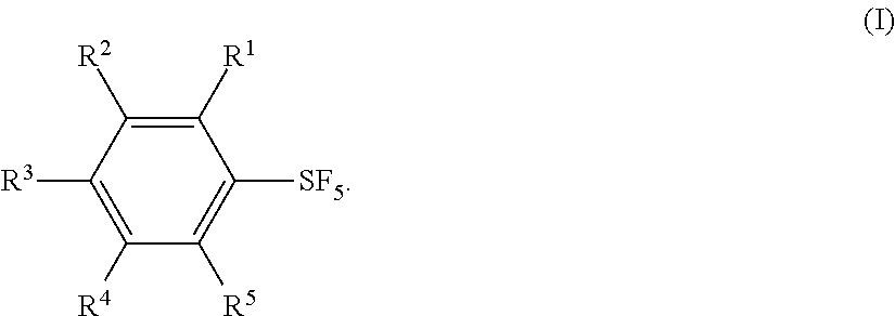
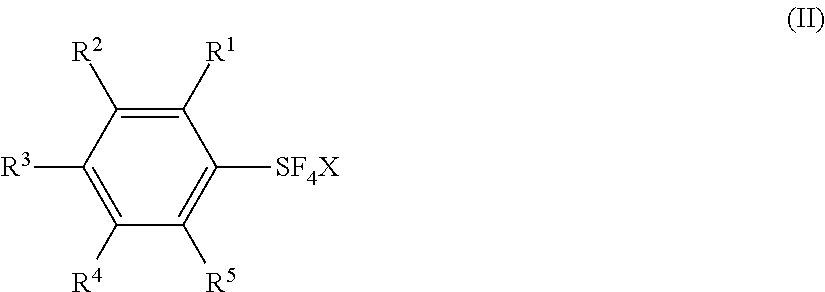
Industrial methods for producing arylsulfur pentafluorides are disclosed. Methods include reacting arylsulfur halotetrafluoride with hydrogen fluoride in the absence or presence of one or more additives selected from a group of fluoride salts, non-fluoride salts, and unsaturated organic compounds to form arylsulfur pentafluorides.

Description

TECHNICAL FIELD[0001]The invention relates to industrial methods useful in the production of arylsulfur pentafluorides.BACKGROUND ART[0002]Arylsulfur pentafluoride compounds are used to introduce one or more sulfur pentafluoride groups into various commercial organic molecules. In particular, arylsulfur pentafluorides are useful (as product or intermediate) in the development of liquid crystals (Eur. J. Org. Chem. 2005, pp. 3095-3100) and as bioactive chemicals such as fungicides, herbicides, insecticides, paraciticides, anti-cancer drugs, enzyme inhibitors, antimalarial agent, and other like materials [see, for example, J. Pestic. Sci., Vol. 32, pp. 255-259 (2007); Chimia Vol. 58, pp. 138-142 (2004); ChemBioChem 2009, 10, pp. 79-83; Tetrahedron Lett. Vol. 51 (2010), pp. 5137-5140; J. Med. Chem. 2011, Vol. 54, pp. 3935-3949; J. Med. Chem. 2011, Vol. 54, pp. 5540-5561; WO 99 / 47139; WO 2003 / 093228; WO 2006 / 108700 A1; US 2005 / 0197370; U.S. Pat. No. 7,381,841 B2; US 2008 / 176865; U.S. Pa...

Claims


Application Information

Patent Timeline
Patent Type & Authority Applications(United States)
IPC IPC(8): C07C321/28
CPCC07C321/28C07C381/00A61P33/00A61P33/06A61P35/00A61P43/00
Inventor UMEMOTO, TERUOSAITO, NORIMICHI
Owner UBE IND LTD
Learn More