Control apparatus for vehicular drive system

a control apparatus and vehicular drive technology, applied in the direction of vehicle position/course/altitude control, process and machine control, instruments, etc., can solve the problems of large amount of sequential shifting operation, large amount of engine speed change to be achieved during sequential shifting operation, and small torque of electric motor provided on the vehicle, etc., to improve the drivability of the vehicle, improve the operating response and smoothness of the vehicle, and reduce the degree of operating response and smoothness.

Inactive Publication Date: 2013-12-05
TOYOTA JIDOSHA KK
View PDF12 Cites 34 Cited by
  • Summary
  • Abstract
  • Description
  • Claims
  • Application Information

AI Technical Summary

Benefits of technology

[0009]According to the first aspect of the present invention described above, the engine speed can be changed with a progress of the above-described discrete shifting operation of the above-described transmission mechanism, by positively utilizing the torque of the engine which increases with an increase of the amount of change of the operating speed of the above-described engine, whereby it is possible to minimize an increase of a sequential shifting time period between moments of initiation and termination of a sequential shifting operation in the form of the above-indicated discrete shifting operation, which increase would take place due to a large amount of change of the operating speed of the engine, assuring a sufficiently high degree of response of the vehicle to the operation by the vehicle operator, so that the drivability of the vehicle in the above-described sequential shifting operation (discrete shifting operation) can be improved. The word “drivability” is interpreted to mean degrees of the operating response and smoothness of the vehicle in accordance with the intention of the vehicle operator, as felt by the vehicle operator. An improvement of the drivability of the vehicle means high degrees of the operating response and smoothness of the vehicle as felt by the vehicle operator, while deterioration of the drivability means low degrees of the operating response and smoothness of the vehicle as felt by the vehicle operator.
[0010]According to a second aspect of the present invention, the control apparatus according to the first aspect of the invention is characterized in that (a) the above-described vehicle is provided with an electric-energy storage device configured to supply and receive an electric energy to and from the above-described electric motor, and (b) the percentage of the torque assigned to the above-described engine in the above-described discrete shifting operation is determined such that the percentage increases with an increase of an amount of limitation of charging or discharging of the electric energy of the above-described electric-energy storage device. According to this second aspect, the engine speed can be changed with the torque of the engine (hereinafter referred to as “engine torque”) at a sufficiently high rate, even when there is a risk that the torque of the electric motor (hereinafter referred to as “motor torque”) is insufficient to change the engine speed at a high rate in the above-described sequential shifting operation, due to limitation of charging or discharging of the electric energy of the electric-energy storage device. Therefore, it is possible to minimize an increase of the above-indicated sequential shifting time period.
[0011]According to a third aspect of the invention, the control apparatus according to the first or second aspect of the invention is characterized in that the percentage of the torque assigned to the above-described engine in the above-described discrete shifting operation is determined such that the percentage increases with a decrease of a temperature of the above-described engine. According to this third aspect, the engine speed can be changed with the engine torque at a sufficiently high rate, even when there is a difficulty of change of the engine speed at a high rate in the above-described sequential shifting operation due to a large rotary resistance (friction) of the engine at a low temperature of the engine. Therefore, it is possible to minimize an increase of the above-indicated sequential shifting time period. When the temperature of the engine is low with an insufficient warm-up operation thereof, for example, the rotary resistance of the engine is relatively large. According to the third aspect of the invention, therefore, the percentage of the torque assigned to the above-described engine is higher before the warm-up operation than after the warm-up operation, for instance.
[0012]According to a fourth aspect of the invention, the control apparatus according to one of the first through third aspects of the invention is characterized in that when a determination is made that the torque of the above-described engine or the above-described electric motor during a change of the operating speed of the above-described engine in the above-described discrete shifting operation is insufficient and that the above-described discrete shifting operation will not be te...

Problems solved by technology

Actually, however, the maximum torque of the electric motor provided on the vehicle is considerably smaller than that of the engine, so that a change of the engine speed with the above-indicated electric motor requires a long length of time from a moment of initiation of the ab...

Method used


Image

  • Control apparatus for vehicular drive system
  • Control apparatus for vehicular drive system
  • Control apparatus for vehicular drive system

Examples


first embodiment

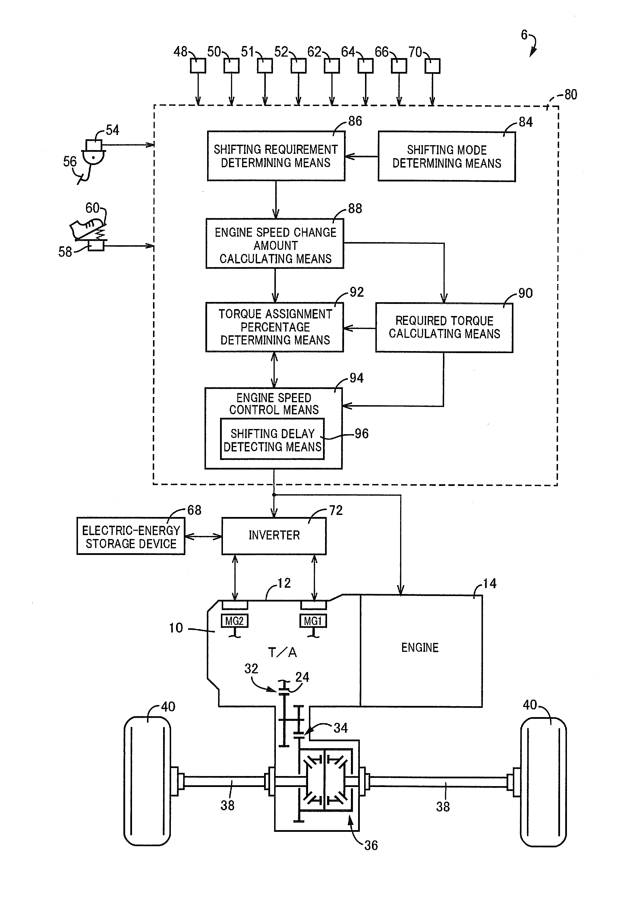
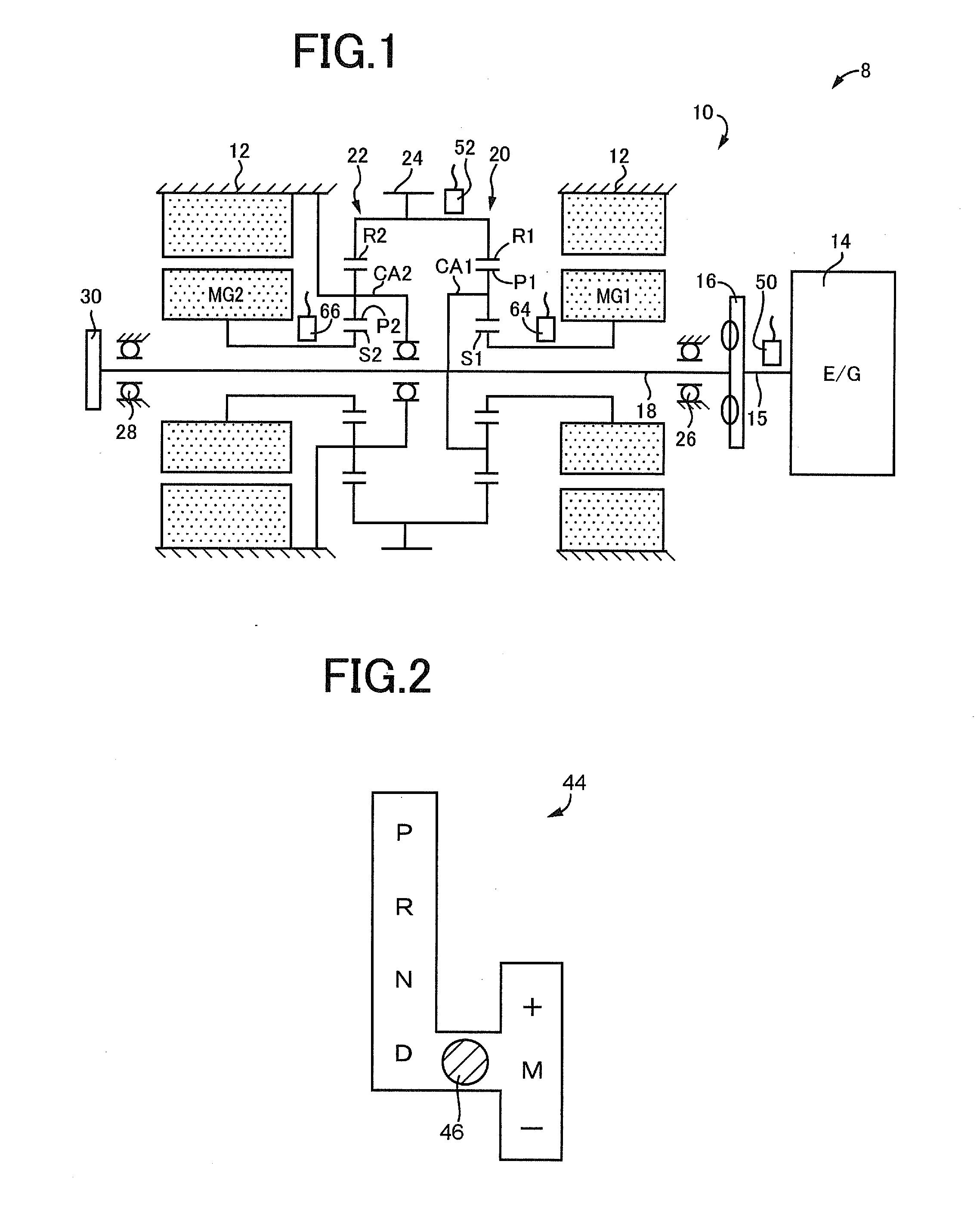
[0035]FIG. 1 is the schematic view for explaining a vehicular drive system 8 to which the present invention is applicable. As shown in FIG. 1, the vehicular drive system 8 is provided with an engine 14 for generating a vehicle drive force, and a vehicular power transmitting device 10 (hereinafter referred to as “power transmitting device 10”) interposed between the engine 14 and drive wheels 40 (shown in FIG. 4). The power transmitting device 10 is a transaxle for transmitting the drive force from the engine 10 to the drive wheels 40. Within a transaxle (T / A) casing 12 (hereinafter referred to as “casing 12”) which is a stationary member fixed to a vehicle body, the power transmitting device 10 is provided with the following elements disposed in the order of description from the side of the engine 14: a damper 16 operatively connected to an output shaft 15 (crankshaft, for instance) of the engine 14 and configured to absorb a pulsating variation of torque received from the engine 14...

second embodiment

[0101]Aspects of the second embodiment different from the first embodiment will be primarily described. FIG. 12 is the schematic view for explaining a vehicular drive system 108 of a hybrid vehicle 106 (hereinafter referred to as a “vehicle 106”) according to the second embodiment, and is the functional block diagram for explaining major control functions of an electronic control device 140 provided to control the vehicular drive system 108. As shown in FIG. 12, the vehicular drive system 8 is provided with the engine 14, a vehicle driving electric motor MGR (electric motor provided according to the present invention), a step-variable automatic transmission 112, a differential gear device 114 equivalent to the differential gear device 36 in the first embodiment, the inverter 72, and the electric-energy storage device 68 electrically connected to the vehicle driving electric motor MGR through the inverter 72. The engine 14, vehicle driving electric motor MGR, automatic transmission 1...


PUM


Abstract

A control apparatus for a drive system of a vehicle, provided with a transmission, and an electric motor operable to change an operating speed of the engine during the process of shifting of the transmission. The control apparatus controls a discrete change of the operating speed of said engine, with at least one of torques assigned to be respectively generated by said engine and said electric motor in a discrete shifting operation of the transmission mechanism which is performed in response to an operation of an operator of the vehicle and in which the discrete change of the operating speed of said engine takes place, includes a torque assignment determining portion configured to determine a percentage of the torque assigned to said engine in said discrete shifting operation such that the percentage increases with an increase of an amount of change of the operating speed of the engine.

Description

TECHNICAL FIELD[0001]The present invention relates to techniques for improving drivability of a vehicle provided with an engine and an electric motor.BACKGROUND ART[0002]There is known a control apparatus for a vehicular drive system provided with a transmission mechanism constituting a part of a power transmitting path between an engine and drive wheels, and an electric motor operable to change an operating speed of the engine in the process of shifting of the transmission mechanism. Patent Document 1 discloses an example of such a control apparatus in the form of a drive control apparatus for a hybrid vehicle. The above-indicated transmission mechanism provided in the vehicular drive system disclosed in this Patent Document 1 is an automatic step-variable transmission which includes a plurality of planetary gear sets and a plurality of frictional coupling elements and which performs shifting actions by engaging and releasing actions of the frictional coupling elements. The above-i...

Claims


Application Information

Patent Timeline
IPC IPC(8): B60W20/00B60W10/08B60W10/10B60W10/06B60L50/16
CPCB60W20/00B60W10/06B60W10/08B60W10/10Y10S903/93B60W20/30B60W30/188B60W2540/165B60W2710/0644B60W2710/0666B60W2710/081B60W2710/083B60K6/445Y02T10/62Y02T10/72B60W30/19B60W20/40B60K6/485
Inventor KATO, SHUNYAMATSUBARA, TOORUKUMAKAZI, KENTATABATA, ATSUSHIHIASA, YASUHIRO
Owner TOYOTA JIDOSHA KK
Why Eureka
Try Eureka