Buoyancy Control System

a control system and buoyancy technology, applied in special-purpose vessels, floating buildings, transportation and packaging, etc., can solve problems such as gas loss, injury or death, and unstable conventional flexible lift bag systems

Active Publication Date: 2013-12-12
SCUBA LAB
View PDF4 Cites 6 Cited by
  • Summary
  • Abstract
  • Description
  • Claims
  • Application Information

AI Technical Summary

Benefits of technology

[0011]Various embodiments of a buoyancy-based lifting system include a flexible lift bag, or any vessel in which the contained gas is responsive to the ambient pressure of the water, configured to be coupled to a load to be lifted; one or more valves that can be used to inflate or deflate the flexible lift bag by adding or removing a compressible fluid to the lift bag; a pressure sensor used to obtain ambient pressure measurements during a lift, i.e. pressure measurements external to the flexible lift bag; and a lift-controller that uses the ambient pressure measurements to estimate impending instabilities during a lift. The lift controller can dynamically stabilize movement of the lifting system by inflating or deflating the lift bag to avoid the impending instabilities. In some embodiments, multiple valves, including one or more inflation valves, one or more deflation valves and one or more manual override valves are included in the buoyancy-based lifting system.

Problems solved by technology

Conventional flexible lift bag systems tend to become unstable during a lift, because the partially-inflated lift bag changes volume inversely with depth, and therefore tends to accelerate upward or downward when displaced even slightly from a position of neutral buoyancy.
The risks of instability include diver entanglement in a rapid, uncontrollable ascent or descent, potentially causing injury or death.
Also, the lift bag, and load being lifted, may broach the surface at high speed, possibly causing the loss of gas from an open-bottom bag, followed by uncontrolled descent.
The high speed ascent or broaching itself may damage the object being lifted.
Using lift bags to overcome seabed suction, or to free mechanically-locked or snagged equipment, can also be problematic, as the amount of buoyant force needed to lift the load becomes suddenly less as soon as the load is freed.
Although rigid volume lifting devices, such as ballast tanks may not suffer from the volume-change instability of flexible lift bags, the rigid volume devices can be excessively cumbersome due to their large size and weight, making them more difficult to transport than flexible lift bags.

Method used


Image

  • Buoyancy Control System
  • Buoyancy Control System
  • Buoyancy Control System

Examples


Embodiment Construction

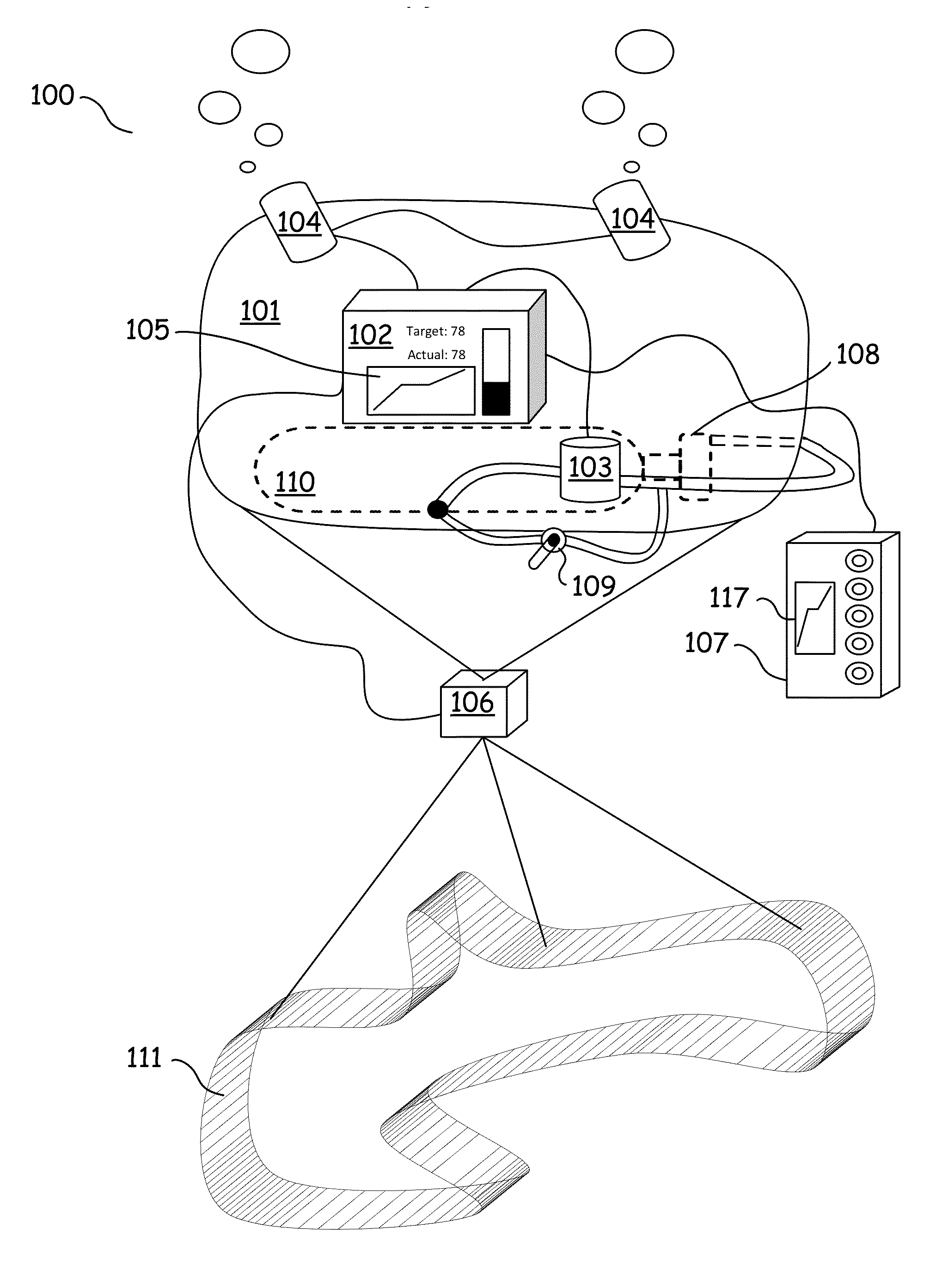
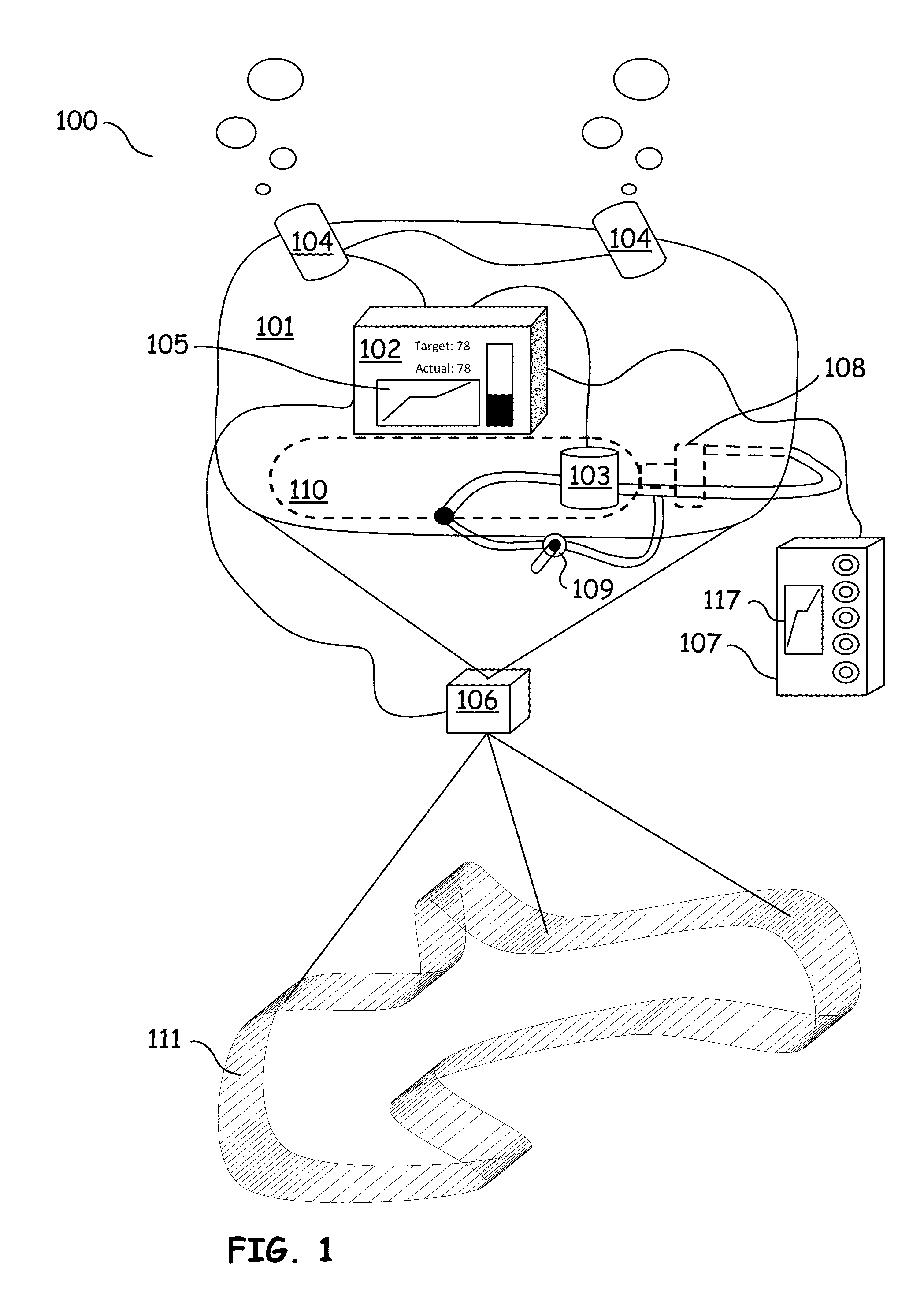
[0025]As used herein, the term “compressible fluid” refers to a gas or liquid used in flexible buoyant lift bags. In general, compressible fluids will expand or contract the volume of a lift bag depending on the pressure present at any particular depth under water. The term gas is used generally throughout this description, but it should be understood that another compressible fluid can, in many instances, be substituted for a gas.

[0026]The terms “lift bag” and “flexible lift bag” may be used interchangeably herein, unless otherwise specified or required by the context of the term, and usually refer to containers with non-rigid-walls, either partially or fully enclosed, used in buoyant lifting systems. For most flexible lift bags, the pressure inside of the lift bag is slightly higher, but approximately equal to the pressure outside of the lift bag, because the walls of the lift bag flex in response to the expansion or contraction of the gas inside, and the pressure outside of the l...


PUM


Abstract

A buoyancy-based lifting system can be dynamically controlled to lift, move, or hold a load an object of arbitrary size at a fixed depth. The control system can control the trajectory of a flexible gas-filled lift bag and attached load by opening or closing inflation and deflation valves based on ambient pressure readings obtained during a lift. Stable control can be achieved and maintained without having to directly measure the actual volume of gas in the lift bag, and without having to accumulate measurements of gas flows into and out of the bag. A controller can pre-determine limits of instability and lift control parameters, then use this information in conjunction with ambient pressure readings to prevent the system from becoming unstable during a lift. User intervention is generally unnecessary to maintain the system's instability.

Description

CROSS REFERENCE TO RELATED PATENTS[0001]This application claims the benefit of U.S. Provisional Application No. 61 / 657,050, filed Jun. 8, 2012 and entitled, “Buoyancy Control System,” and U.S. Provisional Application No. 61 / 663,101, filed Jun. 22, 2012 and entitled, “Buoyancy Control System,” both of which are incorporated herein by reference in their entirety.STATEMENT REGARDING FEDERALLY SPONSORED RESEARCH OR DEVELOPMENT[0002]NOT APPLICABLEINCORPORATION-BY-REFERENCE OF MATERIAL SUBMITTED ON A COMPACT DISC[0003]NOT APPLICABLEBACKGROUND[0004]1. Technical Field[0005]This disclosure relates generally to lifting loads using buoyancy-based lifting systems, and more particularly to controlling buoyancy-based lifts.[0006]2. Description of Related Art[0007]The marine salvage industry, off-shore oil & gas industry, nautical archeology, and military operations often use air lift bags to move or recover objects in bodies of water. Two types of lift bags exist: the open-bottom or parachute-typ...

Claims


Application Information

Patent Timeline
Patent Type & Authority Applications(United States)
IPC IPC(8): B63C7/02
CPCB63C7/02B63B22/22B63C7/10B63G8/001B63G8/24B63B2207/02
Inventor SPARKS, SHANNON PATRICKEARLES, TIMOTHY LEE
Owner SCUBA LAB
Why Eureka
Try Eureka