Valve for injecting fuel

a valve and fuel technology, applied in the direction of valve operating means/release devices, machines/engines, mechanical devices, etc., can solve the problems of high impulse, high cost, and high cost of chrome plating of armatures, and achieve the effects of improving damping characteristics, low cost, and producing very easily

Active Publication Date: 2013-12-12
ROBERT BOSCH GMBH
View PDF10 Cites 5 Cited by
  • Summary
  • Abstract
  • Description
  • Claims
  • Application Information

AI Technical Summary

Benefits of technology

[0010]According to the present invention, magnetic injectors can thus be produced very easily and at low cost without chrome plating, also having, in addition to improved damping chara

Problems solved by technology

Here, high impact impulses can occur, which can cause damage and in particular can cause chipping of the chrome layer.
In addition, the chrome plating of the armature is very cost-intensive, and the metallic co

Method used


Image

  • Valve for injecting fuel
  • Valve for injecting fuel
  • Valve for injecting fuel

Examples


Embodiment Construction

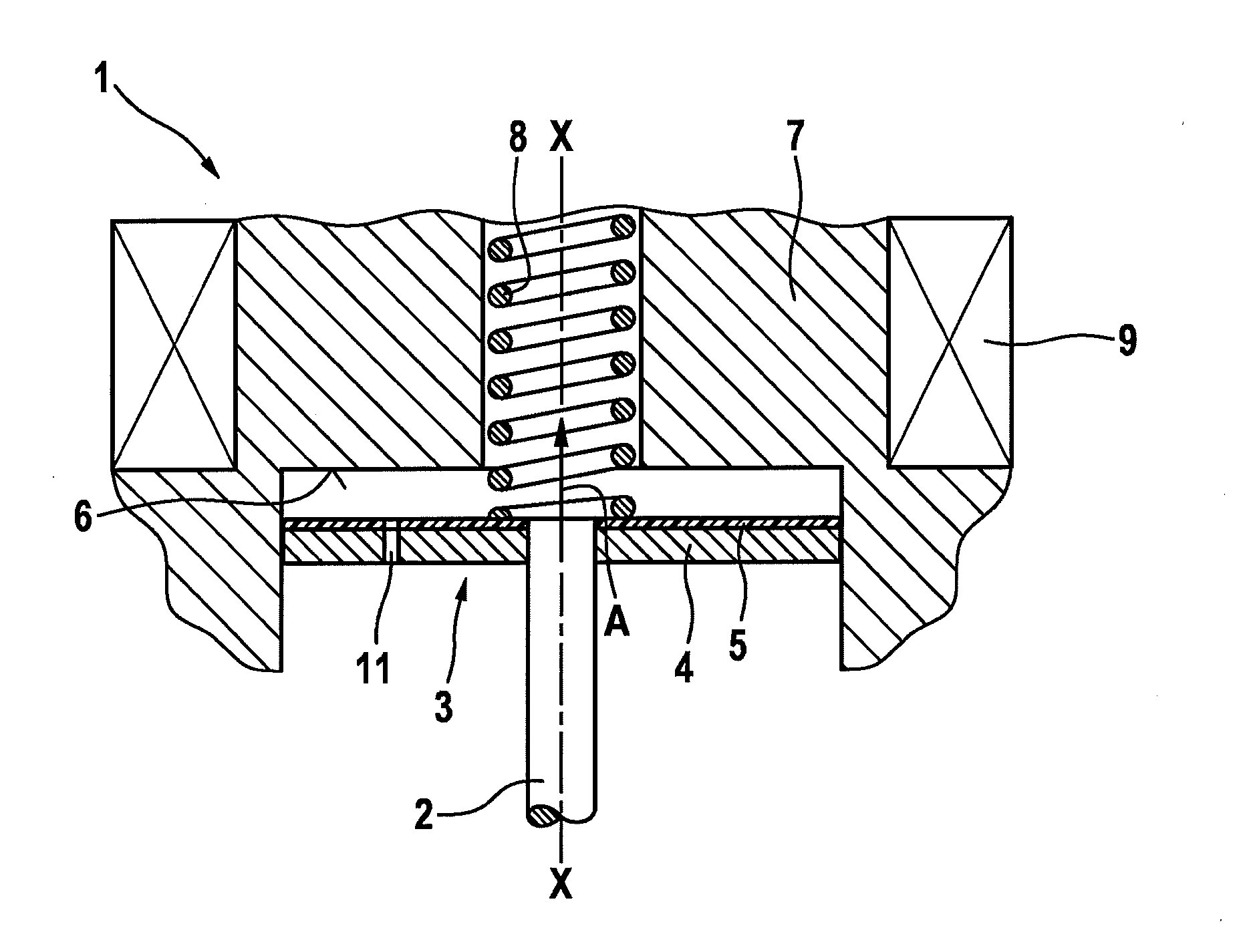
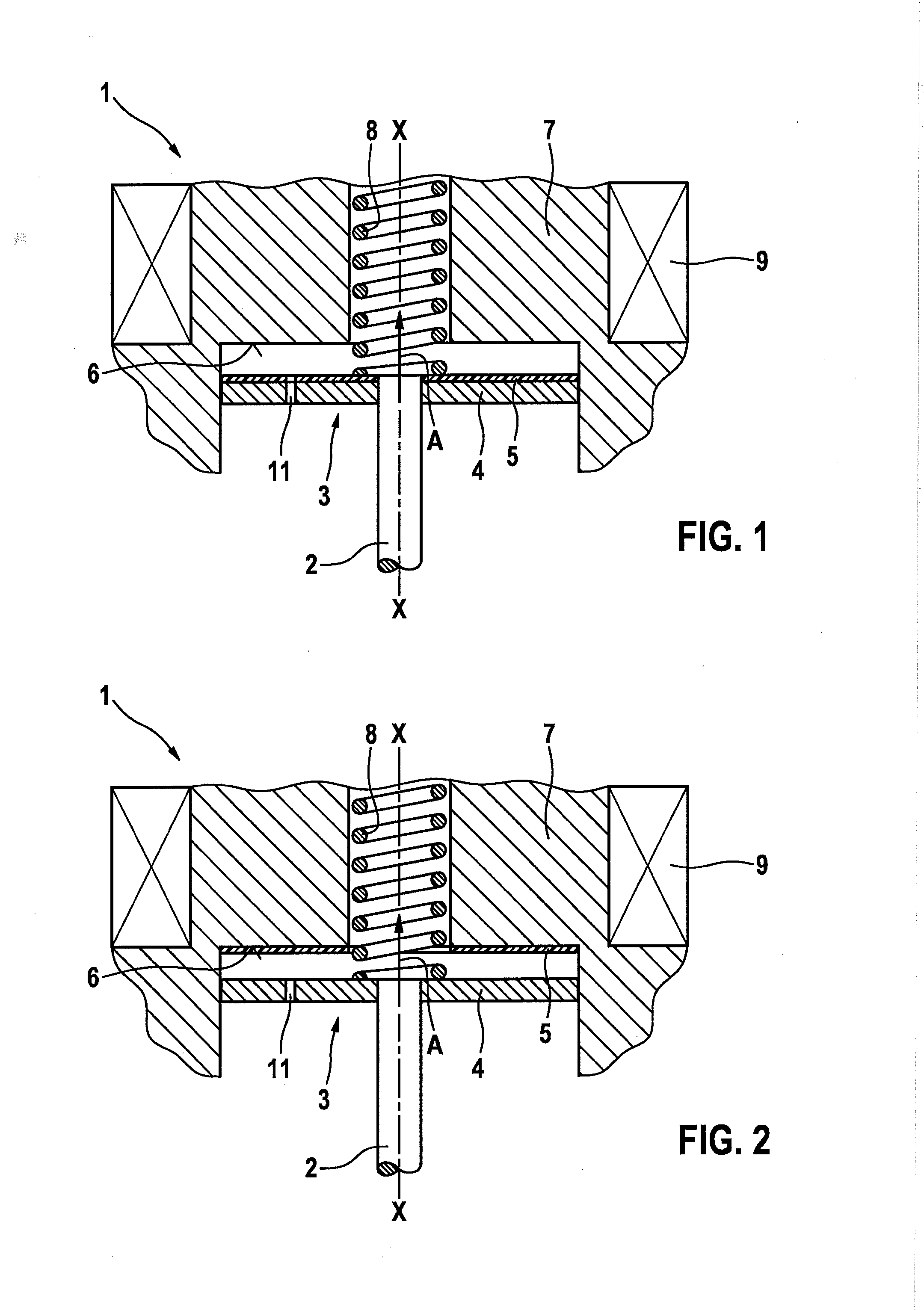
[0016]FIG. 1 shows a sectional view of a magnetic valve 1 according to a first exemplary embodiment for injecting fuel;

[0017]the valve is not shown completely, but only schematically. The valve includes a valve needle 2 as adjustment element and an armature 3 connected to the valve needle. In this way, valve needle 2 moves together with armature 3. In addition, on a housing 7 there is provided a stop 6 that limits a path of armature 3. A resetting of armature 3 takes place using a reset element 8. The valve is a magnetic valve, and further includes a coil 9 that, when current flows through it, moves armature 3 towards stop 6 in the direction of arrow A, thus opening the valve.

[0018]As can be seen in FIG. 1, armature 3 has an armature body 4 fashioned as a disk. On the side of armature body 4 oriented toward stop 6, there is applied a damping element 5 in the form of a damping layer. Here, the damping layer has a thickness of approximately 20 μm, and is shown in exaggerated fashion i...


PUM


Abstract

A valve for injecting fuel, including a valve positioning element, an armature connected to the valve positioning element, a stop that limits a movement of the armature, and a damping element provided between the armature and the stop, the damping element being applied as a damping layer on at least one part of the armature and/or on at least one part of the stop.

Description

FIELD[0001]The present invention relates to a valve for injecting fuel, having a design that is simplified and lower in cost.BACKGROUND INFORMATION[0002]Conventional valves for injecting fuel are available in various embodiments. In magnetic valves, the armature is made of a soft magnetic material that can be produced for example as a rotating part. In order to increase long-term stability, the armature is coated with chrome. When there is a flow of current through the valve, a magnetic field is built up so that a needle fastened on the armature is accelerated and then impinges with a high impulse against a stop, e.g., an inner pole or a housing. Here, high impact impulses can occur, which can cause damage and in particular can cause chipping of the chrome layer. In addition, the chrome plating of the armature is very cost-intensive, and the metallic component chrome also transmits sound without damping it. In addition, the conventional armatures have a high mass, resulting in a lar...

Claims


Application Information

Patent Timeline
IPC IPC(8): F02M51/06
CPCF02M51/061F02M63/0017F02M2200/09F02M2200/306
Inventor PILGRAM, GUIDO
Owner ROBERT BOSCH GMBH
Why Eureka
Try Eureka