LED illumination device for fluorescent light fixture

a fluorescent light fixture and led illumination technology, which is applied in the field of illumination devices, can solve the problems of not being able to lighten, limit the number and place of emergency lights to be installed, and achieve the effects of reducing the number of emergency lights, and reducing the number of lights

Inactive Publication Date: 2013-12-12
NOGUCHI HINOKI
View PDF5 Cites 35 Cited by
  • Summary
  • Abstract
  • Description
  • Claims
  • Application Information

AI Technical Summary

Benefits of technology

[0017]In accordance with the present invention defined in claim 1, when a power supply via the first power supply circuit is interrupted without normal light-out operation by the light switch, which should be in an emergency such as power supply shutdown, the LED illumination device is controlled in such a manner that the battery is driven to lighten the LED's, so that all of the LED illumination devices installed in an area of the power supply shutdown can be lightened, which could not have been achieved in the prior art solution wherein only a limited number of the emergency lights could be lightened in the power supply shutdown area. Therefore, even when a power supply is interrupted due to an earthquake or a fire in an underground railway or an underground shopping area, for example, everybody in said area can take refuge in safety and at ease. In addition, even when the illumination devices are suddenly turned off due to a power supply shutdown in an opening shop or an office during business hours, the drive mode will soon be switched to the battery drive mode so that all of the LED illumination devices will be lightened in a moment, thereby posing no problem for their normal business.
[0018]In accordance with the present invention defined in claim 2, when the LED's are lightened via the first power supply circuit in the normal illumination mode, a surplus power is supplied to the battery so as to charge the same, whereas when the battery reaches the predetermined upper threshold, the drive mode is switched to the battery drive mode wherein the LED's are lightened by he battery. Accordingly, there is no power consumption as far as the illumination device operates in the second illumination mode. For example, when a control cycle is determined such that the first illumination mode runs in one hour for the lightening and the battery charge and the second illumination mode runs in three hours for the lightening with the battery, even in 24-hours continuous lightening, a power is consumed only in total six hours of the first illumination mode operation. The LED illumination device itself is less power-consumptive (the LED's works at the order of 22 W, which is less than a half of 51 W, for example, of the existing fluorescent lamps). For these reasons, the power consumption is about 1/10 or less, providing a great power-saving effect.
[0019]In accordance with the present invention defined in claim 3, there is provided a charge controller that constantly monitors the residual amount of the battery. Therefore, the switch controller operates in response to a signal from the charge controller to discriminate quickly and accurately that the residual amount of the battery reaches the upper threshold or the lower t...

Problems solved by technology

However, they are not lightened in an emergency such as a power supply shutdown.
However, the conventional emergency lights have been installed individually from the normal illumination devices, which should in pra...

Method used


Image

  • LED illumination device for fluorescent light fixture
  • LED illumination device for fluorescent light fixture
  • LED illumination device for fluorescent light fixture

Examples


Embodiment Construction

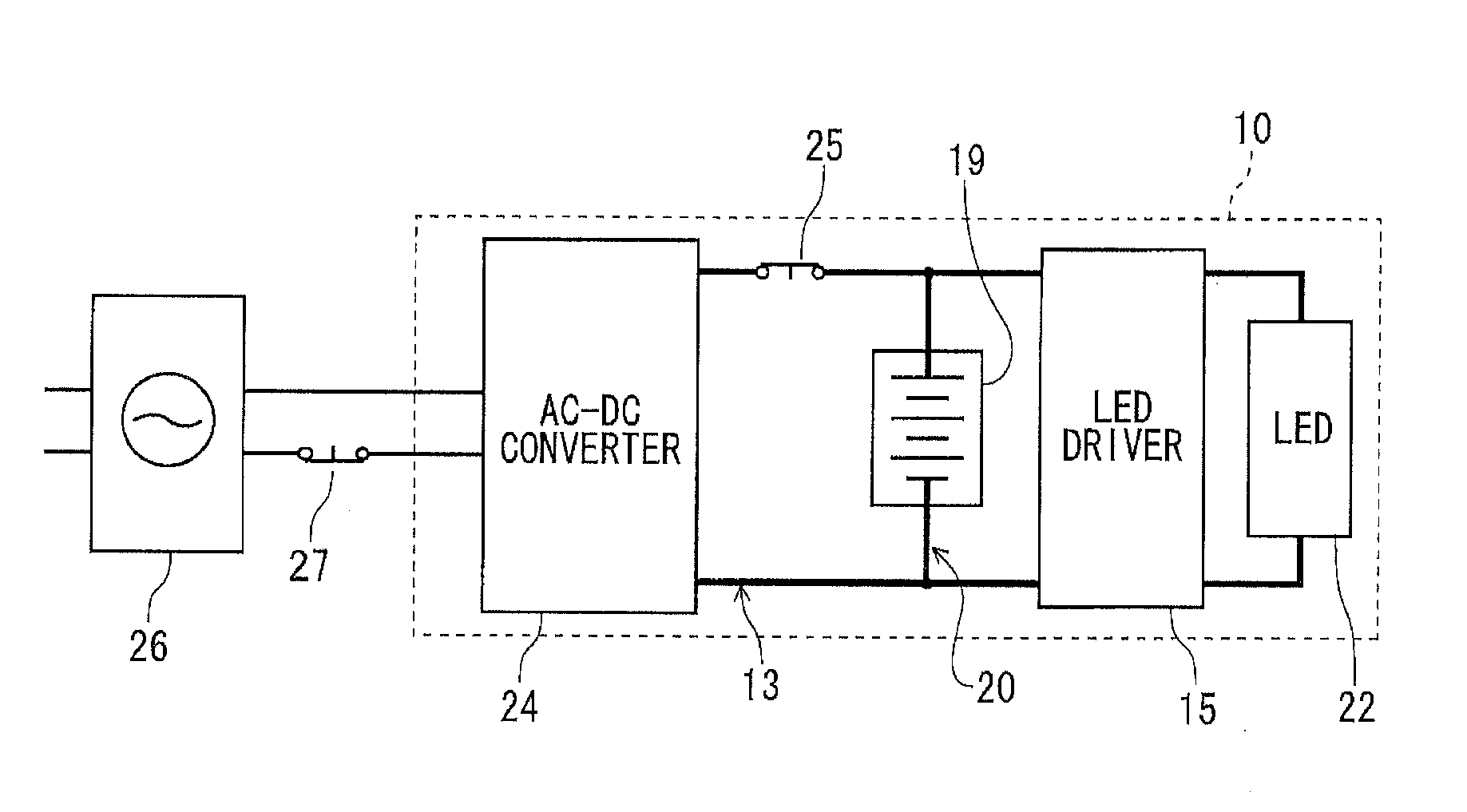
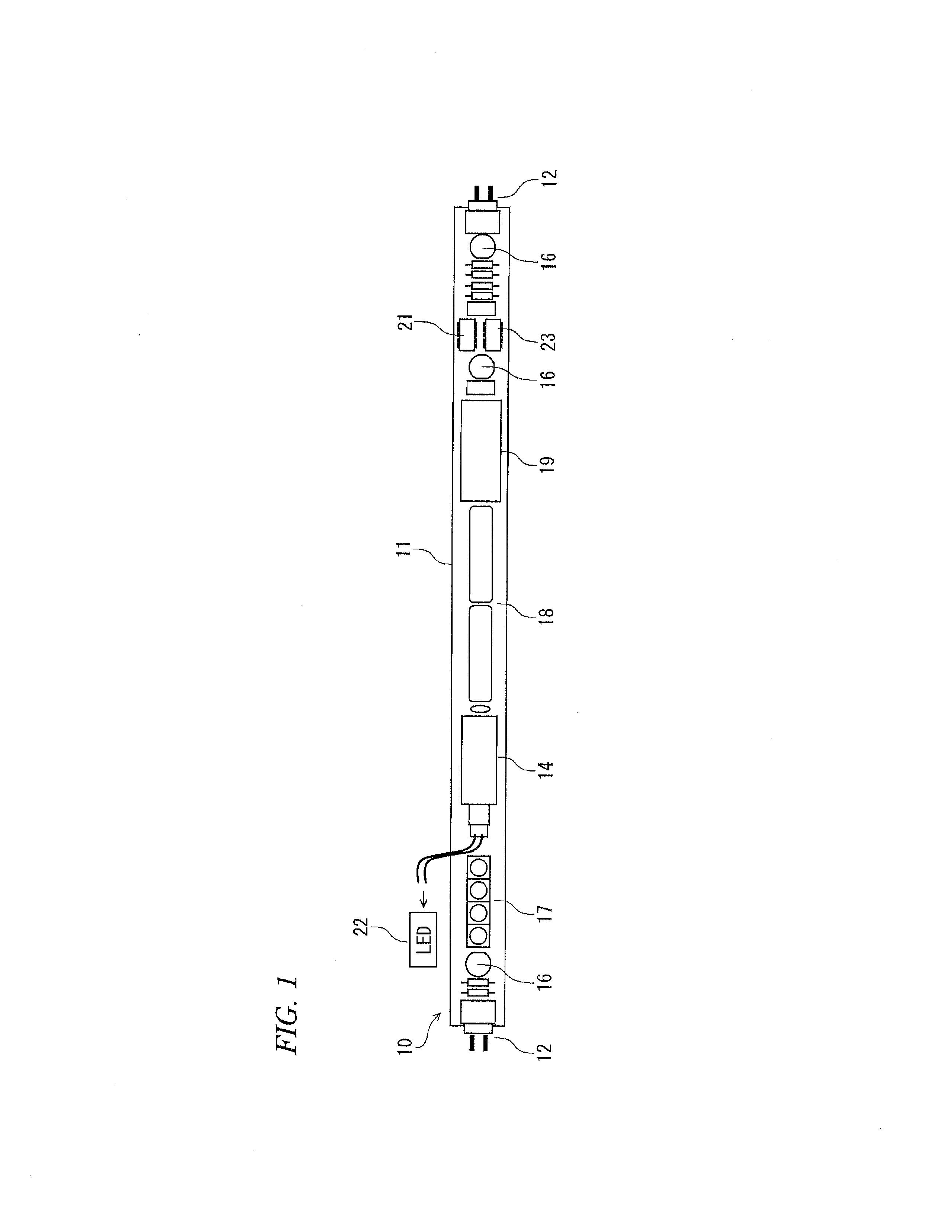
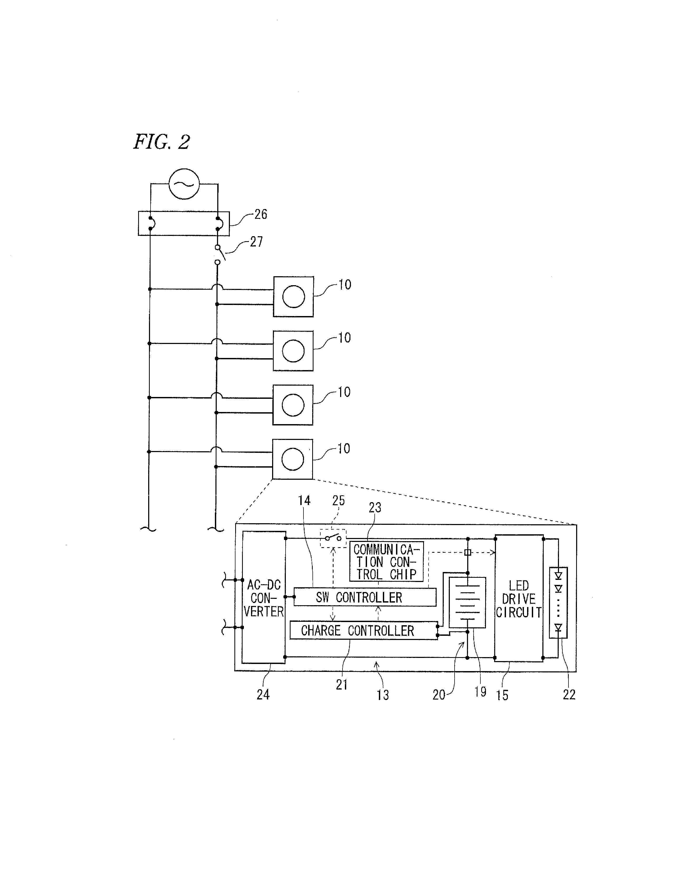
[0040]Several embodiments of the present invention will be described in detail in reference to FIG. 1 and FIG. 2. An LED illumination device 10 is usable in substitution of the existing fluorescent lamp, which has the same size and shape as those of the existing fluorescent lamp and may be fitted between a pair of sockets already installed for the existing fluorescent lamp. The LED illumination device 10 has a cover 11 of substantially a cylindrical cross-section, in which an LED mount base (not shown) for mounting LED's thereon is securely contained. The light emitting from the LED's is transmitted through or diffused by the cover 11 for illumination. In one embodiment, the cover 11 is divided into two substantially half-around parts, one comprising a cover member made of plastic material having light transparency, light semi-transparency or light diffusion property, such as polycarbonate, and the other comprising a heat sink made of heat radiation property, such as aluminum. The L...


PUM


Abstract

An LED illumination device that can be mounted between a pair of sockets provided to a fluorescent light fixture is provided with a first power source circuit that illuminates an LED using DC power obtained by converting and rectifying AC power supplied from the sockets, and a second power source circuit that illuminates the LED using an internal battery. An IC chip installed in the illumination device detects a first current conduction state in two AC power lines that supply the AC power necessary to drive the first power supply circuit and a second current conduction state in another AC power line, and, on the basis thereof, determines whether the device is in a normal illumination mode, a normal off mode, or an emergency illumination mode. On the basis of the determination results, the LED illumination device is controlled according to the mode. When in the emergency illumination mode, the LED is illuminated by the second power source circuit, and the LED illumination device functions as an emergency light.

Description

FIELD OF INVENTION[0001]The present invention relates to an illumination device using a LED (light emitting diode) light source, which is usable in substitution of an existing fluorescent lamp.BACKGROUND ART [0002]Fluorescent lamps have been frequently used as indoor and outdoor illumination devices. However, they are not lightened in an emergency such as a power supply shutdown. Accordingly, the Building Standards Act of Japan requires that there should be installed emergency lights in commercial facilities and accommodations for the purpose of evacuation guidance.[0003]However, the conventional emergency lights have been installed individually from the normal illumination devices, which should in practice limit the number and place of the emergency lights to be installed. This means that, in an emergency, only a small number of the emergency lights are lightened in darkness at limited places. Let us imagine that a power supply is accidentally interrupted due to an earthquake or fi...

Claims


Application Information

Patent Timeline
IPC IPC(8): H05B37/02H02J9/06H05B44/00
CPCH05B37/02H02J9/06F21S9/022H02J9/02H02J9/061F21Y2103/10F21Y2115/10F21K9/278H05B45/10H05B47/105Y02B20/30H05B47/17
Inventor NOGUCHI, HIROKAZU
Owner NOGUCHI HINOKI
Why Eureka
Try Eureka