Variable magnification optical system and imaging apparatus

a magnification optical system and variable magnification technology, applied in the field of variable magnification optical systems and imaging apparatuses, can solve the problems of fierce development competition, achieve high optical performance, small and structured, and low cost

Inactive Publication Date: 2013-12-12
FUJIFILM CORP
View PDF4 Cites 23 Cited by
  • Summary
  • Abstract
  • Description
  • Claims
  • Application Information

AI Technical Summary

Benefits of technology

[0057]According to the first variable magnification optical system of the present invention, a negative first lens group, a stop and a positive second lens group are arranged in this order from an object side. Further, a distance between the first lens group and the second lens group in an optical axis direction becomes shorter when magnification is changed from a wide-angle end to a telephoto end. Further, the stop is fixed relative to an image plane during magnification change, and the structure of the first lens group is appropriately set. Especially, a positive lens is arranged on the most object side in the first lens group, and the material of the positive lens is selected to satisfy formula (1). Therefore, it is possible to realize a variable magnification optical system that is small and structured at low cost, and in which high optical performance is secured while the optical system has a large relative aperture, and that has a relatively medium-telephoto-type variable magnification range.
[0058]According to the second variable magnification optical system of the present invention, a negative first lens group, a stop and a positive second lens g

Problems solved by technology

Since a market for surveillance cameras sharply expanded in

Method used


Image

  • Variable magnification optical system and imaging apparatus
  • Variable magnification optical system and imaging apparatus
  • Variable magnification optical system and imaging apparatus

Examples


Embodiment Construction

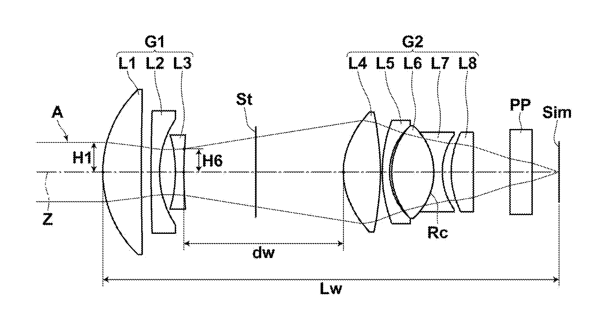
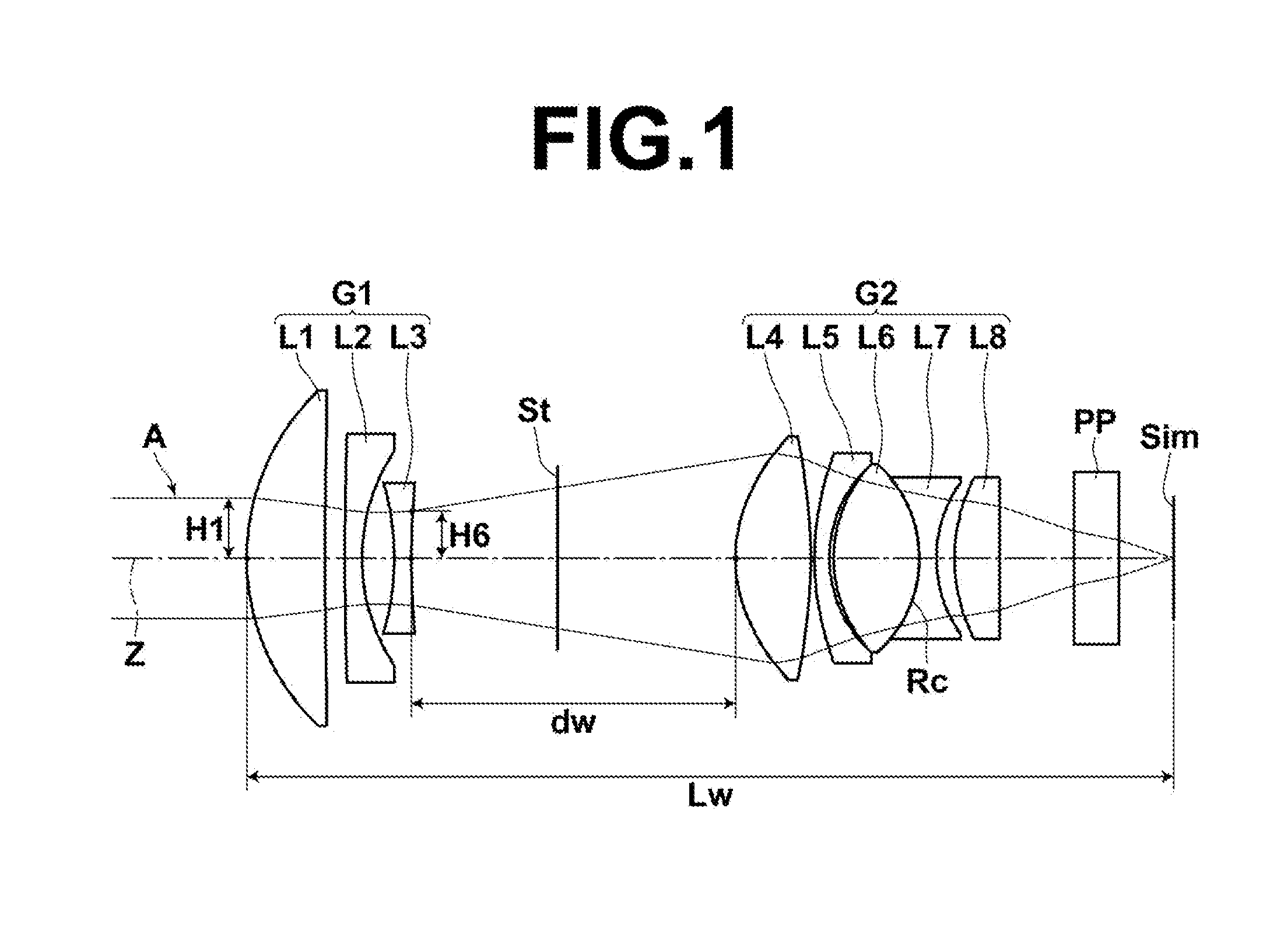
[0082]Hereinafter, embodiments of the present invention will be described in detail with reference to drawings. FIG. 1 is a cross section illustrating a structure example of a variable magnification optical system according to an embodiment of the present invention at a wide-angle end when the optical system is focused on an object at infinity. The example illustrated in FIG. 1 corresponds to a variable magnification optical system in Example 1, which will be described later. In FIG. 1, the left side is the object side, and the right side is the image side. In FIG. 1, axial rays A are also illustrated.

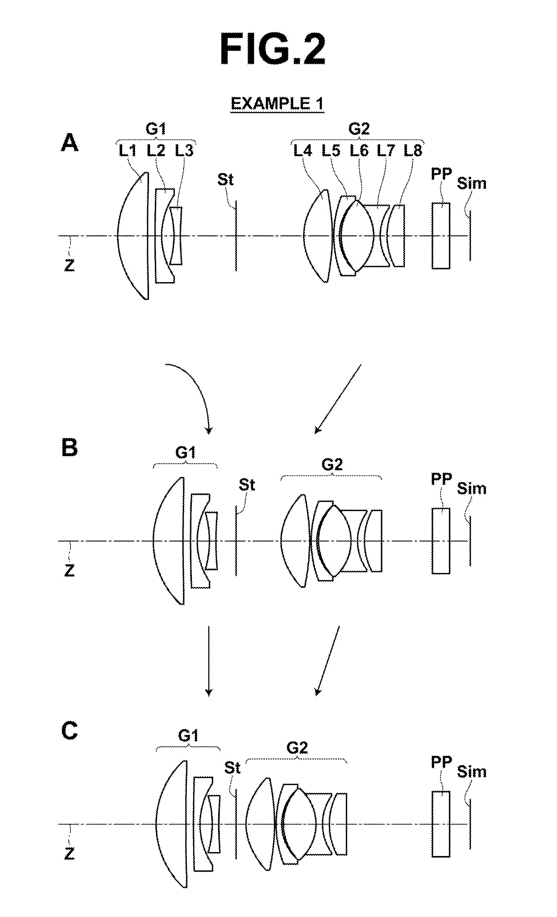
[0083]The variable magnification optical system consists of first lens group G1 having negative refractive power, aperture stop St and second lens group G2 having positive refractive power, which are in this order along optical axis Z from an object side. A distance between first lens group G1 and second lens group G2 in an optical axis direction becomes shorter when magnification is c...


PUM


Abstract

A variable magnification optical system consists of a negative first lens group, a stop that is fixed relative to an image plane during magnification change, and a positive second lens group, which are in this order from an object side. A distance between the first lens group and the second lens group in an optical axis direction becomes shorter when magnification is changed from a wide-angle end to a telephoto end. The first lens group consists of a positive lens having a convex object-side surface and two negative lenses, in this order from the object side. The variable magnification optical system satisfies the following formula (1) about Abbe number νd1 of the positive lens in the first lens group for d-line:
25.5<νd1<50  (1).

Description

BACKGROUND OF THE INVENTION[0001]1. Field of the Invention[0002]The present invention relates to a variable magnification optical system and an imaging apparatus. In particular, the present invention relates to a variable magnification optical system that is usable in a video camera, an electronic still camera and the like, and appropriate especially for a surveillance camera, and an imaging apparatus including the variable magnification optical system.[0003]2. Description of the Related Art[0004]Conventionally, surveillance cameras have been used to prevent crimes, to record and the like, and variable magnification optical systems for CCTV (Closed-circuit Television) have been used, as optical systems for surveillance cameras. Such variable magnification optical systems for CCTV need to have compact lens structure and to be producible at low cost. Further, the specifications of the variable magnification optical systems need to be able to cover a high angle-of-view region through a...

Claims


Application Information

Patent Timeline
IPC IPC(8): G02B15/14
CPCG02B15/14G02B15/177G02B15/1425G02B15/142
Inventor ONO, KAZUNORI
Owner FUJIFILM CORP
Why Eureka
Try Eureka