Multi-Level Connector and Use Thereof that Mitigates Data Signaling Reflections

a multi-level connector and signaling technology, applied in the direction of coupling device connection, printed circuit, two-part coupling device, etc., can solve the problem of negative impact on the overall system performance of the data processing system, and still adversely affect the system performance. problem, to achieve the effect of mitigating undesired signal reflection

Inactive Publication Date: 2013-12-12
IBM CORP
View PDF25 Cites 17 Cited by
  • Summary
  • Abstract
  • Description
  • Claims
  • Application Information

AI Technical Summary

Benefits of technology

[0028]FIG. 10 depicts an alternative embodiment where the first/partial level/depth provides a shunting/closed contact for electrical connection to other connector

Problems solved by technology

As shown above and summarized in FIG. 5, a problem exists when all card connectors are not populated with cards due to undesirable stub-reflections that adversely impact the maximum operational speed of the bus, thus negatively impacting overall system performance of a data processing system.
Also note in FIG. 5 that when only one DIMM is popu

Method used


Image

  • Multi-Level Connector and Use Thereof that Mitigates Data Signaling Reflections
  • Multi-Level Connector and Use Thereof that Mitigates Data Signaling Reflections
  • Multi-Level Connector and Use Thereof that Mitigates Data Signaling Reflections

Examples


Embodiment Construction

[0029]As will be appreciated by one skilled in the art, aspects of the present invention may be embodied as a system or methodology. Aspects of the present invention are described below with reference to flowchart illustrations and / or block diagrams of methods and apparatus (systems) according to embodiments of the invention.

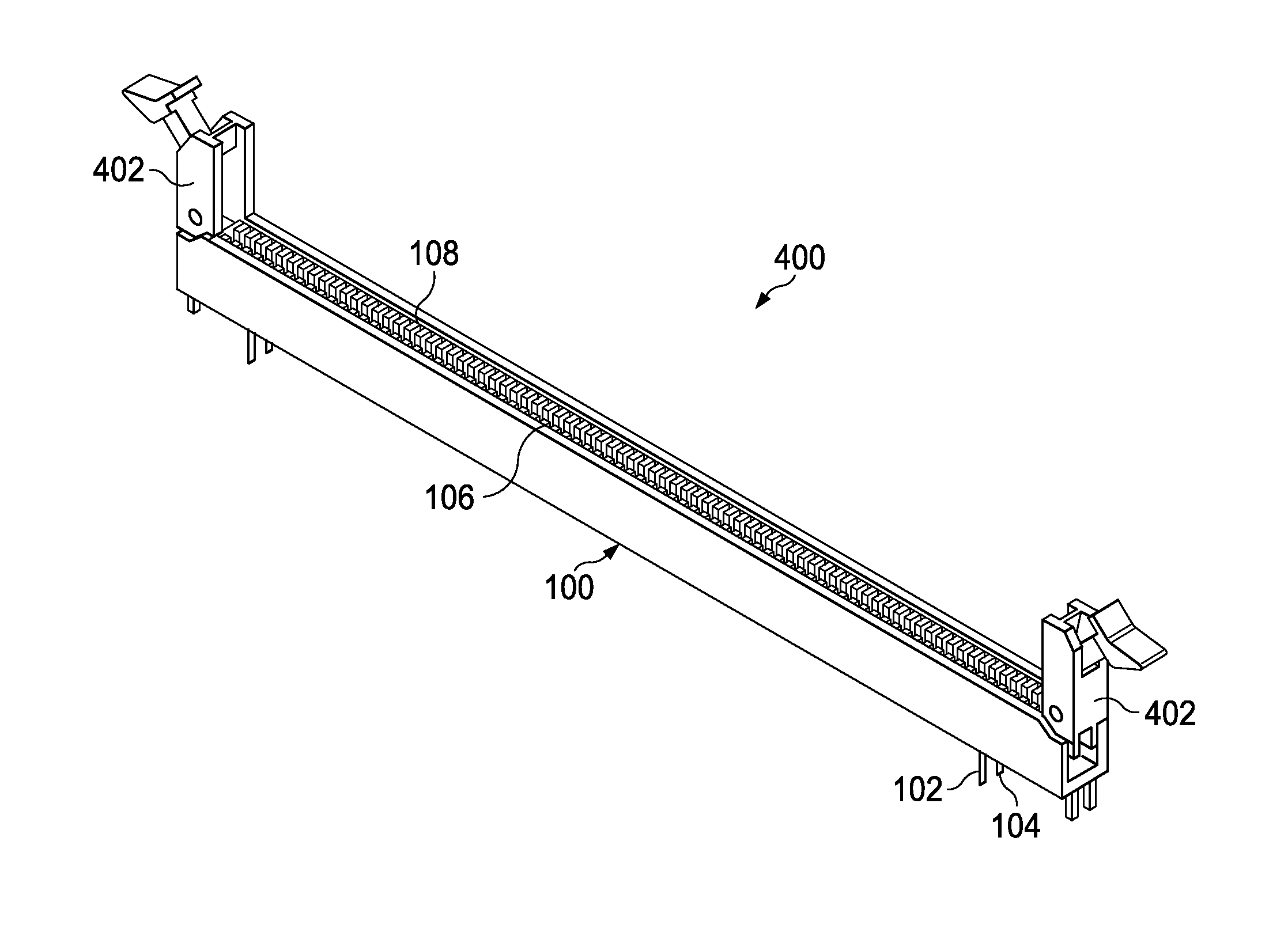
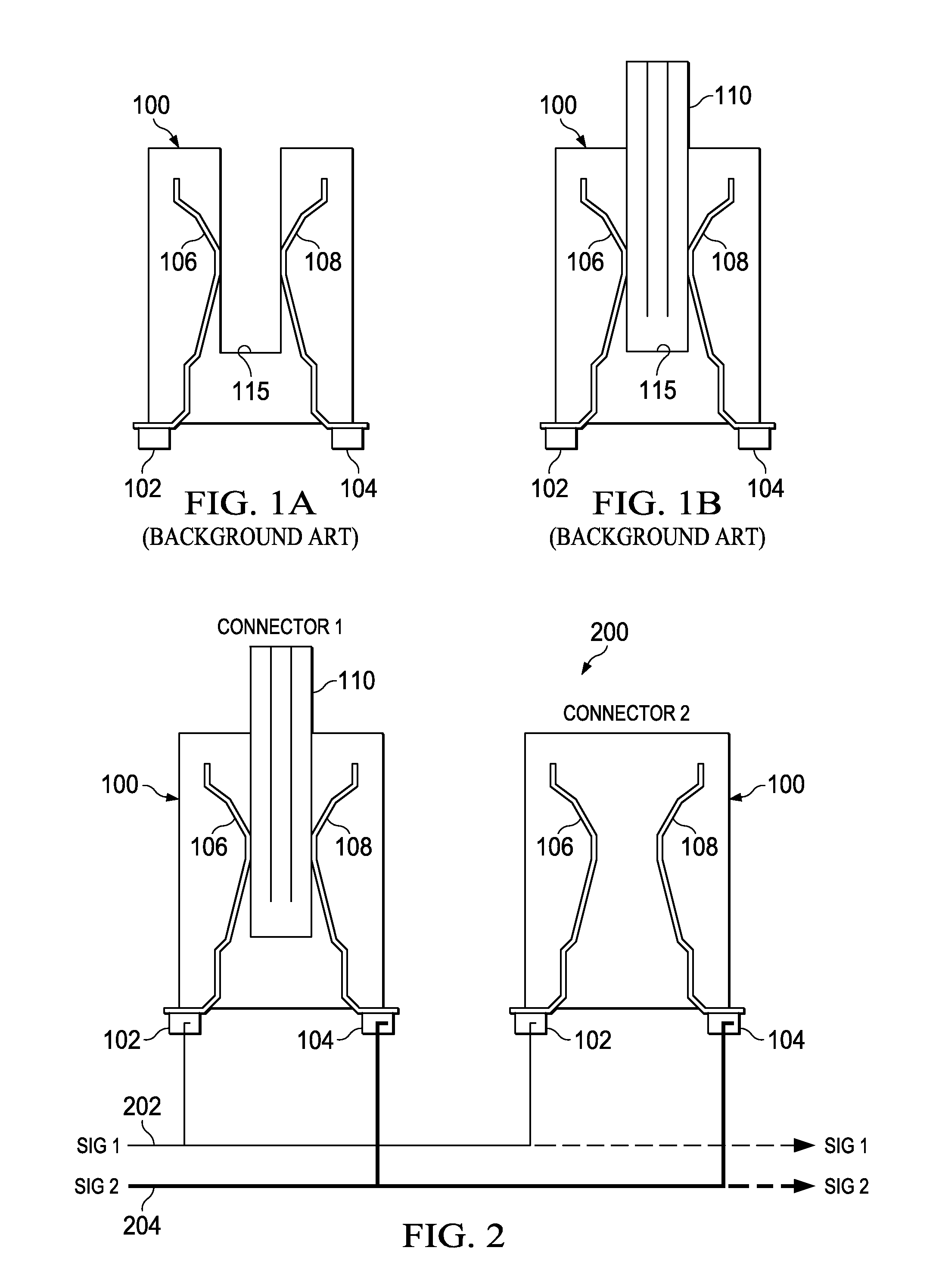
[0030]Referring now to FIGS. 6A, 6B, and 6C, there is shown a near-end populated configuration, a two DIMM populated configuration, and a fully populated configuration according to a preferred embodiment, respectively, that provides an improved connector with dual-contact pins C1, C2 and C3 for connecting bus lines to a card such as a memory card or media card. In particular, an apparatus is provided that comprises a multi-level connector comprising a latching device having a plurality of insertable latch positions. In a preferred embodiment, two (2) different physical levels are provided, although more are possible. When a card / module is only partially inserted...


PUM

PropertyMeasurementUnit
Electrical conductoraaaaaaaaaa
Heightaaaaaaaaaa
Levelaaaaaaaaaa

Abstract

An improved electrical connector for connecting bus lines to a card such as a memory card or media card, including a multi-level connector comprising a latching device having a plurality of insertable latch positions that advantageously allows for selectively connecting or isolating an electrical path to an adjoining connector. The connectors of unpopulated DIMM slots are disconnected from the network along with the traces that would normally form a stub with associated undesirable signal reflections that would otherwise disturb the signal transmitted to the receiving end if not properly terminated. The contacts of the edge connector itself are used as a means to selectively connect or disconnect adjacent/downstream cards in a serially cascaded architecture. The burden of the stubs due to unpopulated card slots and the need to place one card at the far end of the network are thus eliminated.

Description

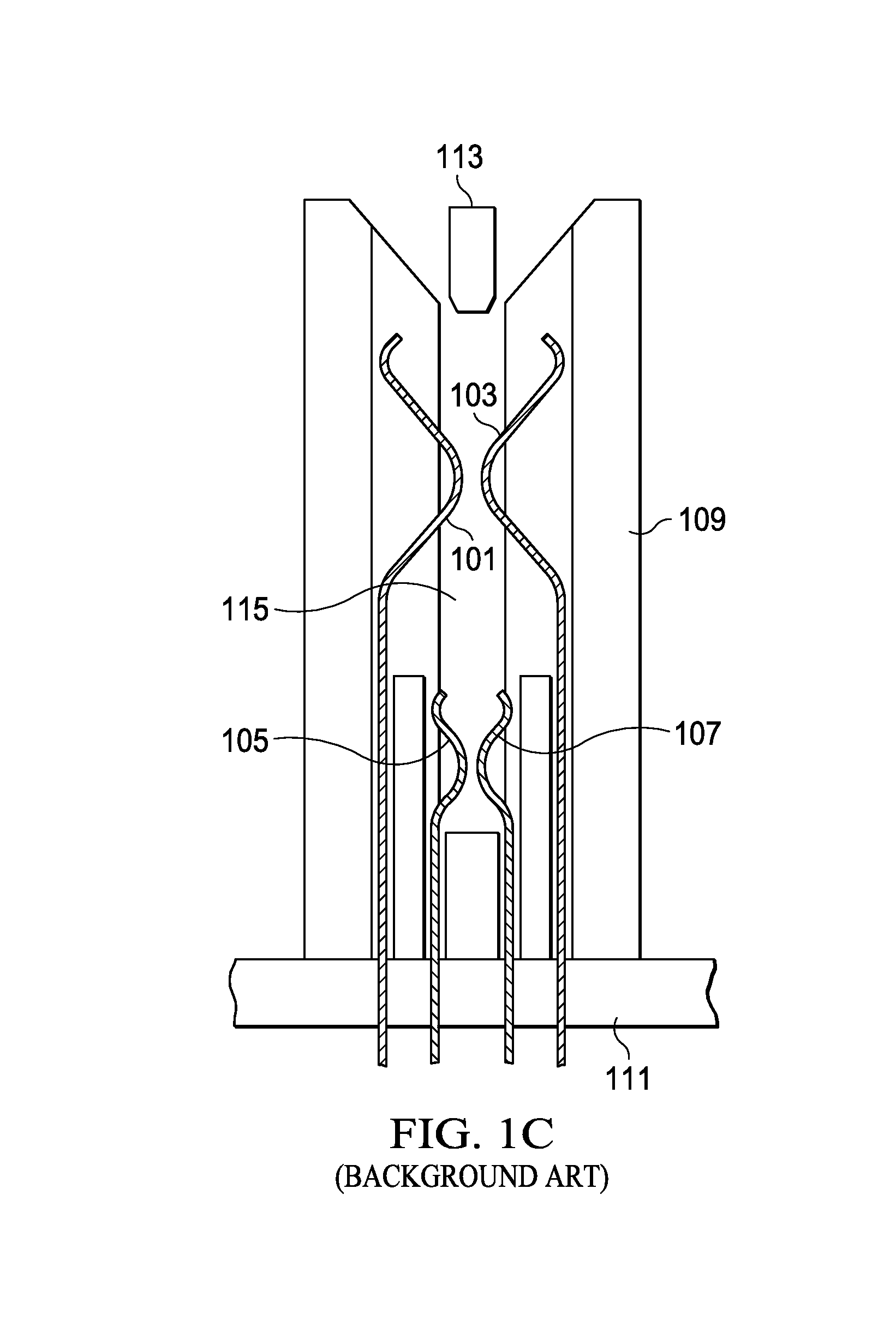
BACKGROUND OF THE INVENTION[0001]1. Field of the Invention[0002]The disclosure relates generally to apparatus and techniques for mitigating signal reflections for signals in a data processing system, and more specifically relates to a connector and associated connector usage that mitigates signal reflections by eliminating stubs in a signal path.[0003]2. Description of the Related Art[0004]As processor speeds increase, there is a growing need to make improvements in the card and connector interface that connect to a plurality of cards and connects. As but one example, dual inline memory modules (DIMM) are plugged into various DIMM connectors on a system or motherboard to increase the amount of memory that is usable in a data processing system. The DIMM connectors are typically connected in a serial fashion on the system or motherboard, and introduce reflection-points or stubs in the electrical path or bus. FIG. 1A shows a traditional DIMM connector 100 without a DIMM card inserted w...

Claims


Application Information

Patent Timeline
IPC IPC(8): H01R12/71H01R24/28
CPCH01R12/716H01R29/00Y10T29/49117H01R13/6273H01R13/6586
Inventor HASSE, MICHAEL D.NA, NANJUPHAM, NAM H.WALLS, LLOYD A.
Owner IBM CORP
Why Eureka
Try Eureka