Intraocular implant

a technology of intraocular lens and lens, which is applied in the field of intraocular lens, can solve the problems of difficulty in accurately defining the position of the lens in the z-direction, difficulty in accurately defining the optical power required for the artificial lens, and difficulty in accurately defining the optical power.

Active Publication Date: 2013-12-12
STEVENS
View PDF6 Cites 1 Cited by
  • Summary
  • Abstract
  • Description
  • Claims
  • Application Information

AI Technical Summary

Benefits of technology

[0009]One problem associated with these known capsular insert techniques is that it is difficult to centre the lens accurately in the X-Y plane of the eye. The X-Y-Z co-ordinates are shown in FIGS. 8 and 9, where the radius of the lens lies in the X-Y plane and the Z-direction is parallel to the optical axis of the eye. A second problem is that it can be difficult to properly define the position of the lens in the

Problems solved by technology

One problem associated with these known capsular insert techniques is that it is difficult to centre the lens accurately in the X-Y plane of the eye.
A second problem is that it can

Method used


Image

  • Intraocular implant
  • Intraocular implant
  • Intraocular implant

Examples


first embodiment

[0051]In another embodiment of the present invention, the intraocular implant of the first embodiment is not a lens, but a plug or bung. Such an implant is not required to have any optical power, but serves merely to close a fenestration or other aperture in the capsule. An example of this is shown in FIG. 19. Indeed, FIG. 19 shows two examples of different diameter, depending on the size of the fenestration to be closed. It can be seen that this implant is flat and therefore has no optical power. Depending on the position of the fenestration being closed, the plug may also be opaque, partially opaque, translucent or otherwise optically altered from transparent.

[0052]Fenestrations that might be closed off using the plug are, for example, fenestrations introduced into the capsule in order to facilitate the entry of an instrument for evacuating the lens material. In this respect, femtosecond lasers are often used to cut the lens into very small cubes or slices, so that they can be eva...

second embodiment

[0057]A variant of this arrangement is shown in FIGS. 23 and 24, and is based on the Here a pair of oppositely placed lugs 100 is provided as integral extensions to two of the first projections 76 or second projections 78. These engage with holes or voids in the capsule similar to those shown in FIG. 22. In a further variant of this variant arrangement, the lugs are instead each provided between two adjacent projections 76 or 78, as shown by the dotted-line projections 102 in FIG. 24. These projections 102 are therefore dedicated solely to carrying the lugs, whereas in the first arrangement the projections 76 (or 78) act both as protrusions for engagement with the lip of the capsulotomy and as carriers of the lugs for engagement with the capsule.

[0058]Although the lugs shown in FIGS. 20, 21 and 23 are of a length such as to end up approximately flush with the radially outer part of the projecting portion—e.g. flush with the projections 78 in FIG. 23, and similarly in FIG. 21—in pra...


PUM


Abstract

An intraocular implant for placement in the eye, e.g. as part of a cataract operation or crystalline lens extraction refractive operation, has at a peripheral portion of the implant a groove which engages with the lip of a single capsulotomy only formed in the lens capsule of the eye. The implant will normally be a lens, but may instead be a bung or plug for occluding an opening made in the capsule. The groove may be a continuous groove around the periphery of the implant, or there may be a series of individual spaced-apart grooves formed as projections protruding from the periphery. Instead of a single groove, a pair of axially spaced-apart grooves may be provided, which engage with respective capsulotomies formed in an anterior and a posterior part of the capsule. The posterior groove is preferably of a smaller mean diameter than the anterior groove

Description

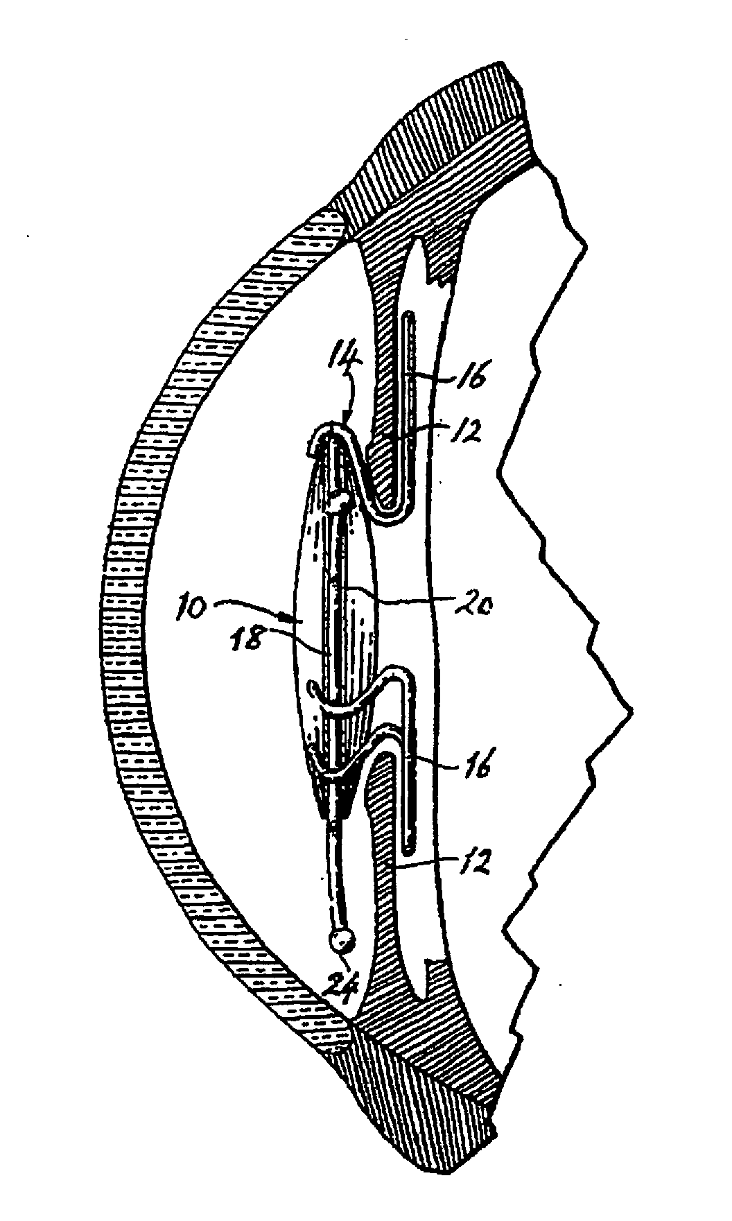
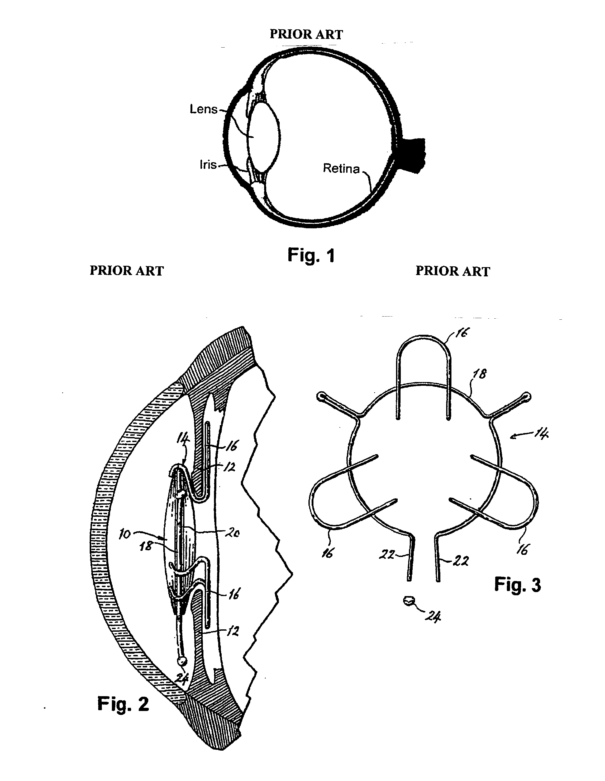
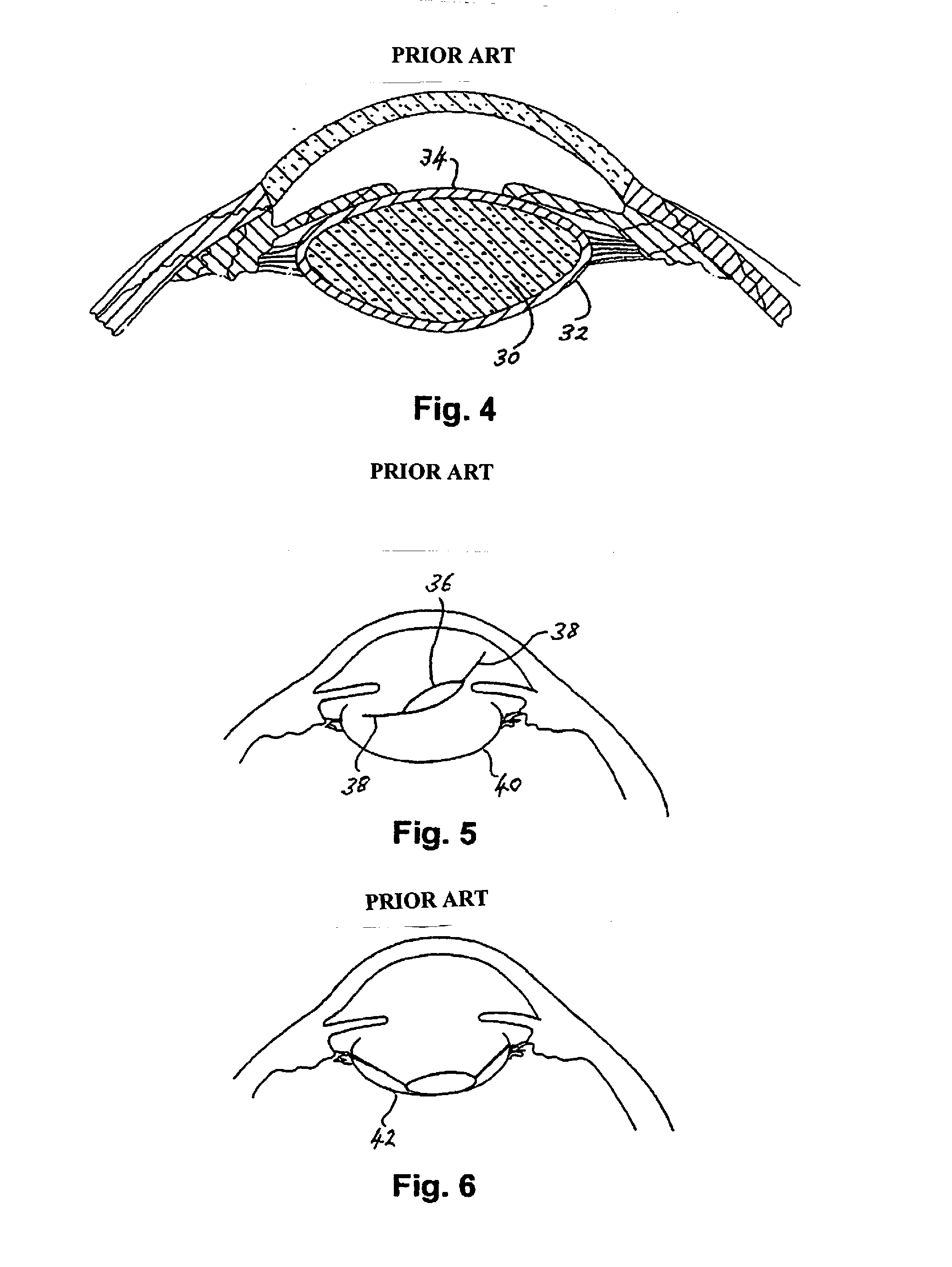
FIELD OF THE INVENTION[0001]The invention relates to an intraocular implant, and in particular to an intraocular implant for use in cataract operations or refractive crystalline lens extraction operations generally.BACKGROUND OF THE INVENTION[0002]The cataract condition is a well known eye ailment, which these days, is easily treatable through surgery. The condition involves an opacification, yellowing or clouding of the natural crystalline lens (see FIG. 1), which is situated just behind the iris and serves to focus the incoming image onto the retina at the back of the eye.[0003]The surgical procedure involves the removal of the opaque natural lens and its substitution by an artificial lens having the required focusing effect.[0004]One way of achieving this is described in U.S. Pat. No. 3,925,825. FIGS. 2 and 3 correspond to FIGS. 1 and 2 of this patent, and show the placing of a lens 10 anterior to the iris 12. The lens is held in place against the iris by a haptic section 14. The...

Claims


Application Information

Patent Timeline
IPC IPC(8): A61F2/16
CPCA61F9/007A61F2002/1681A61F2220/0008A61F2/14A61F9/0017A61F2/1632A61F2/16
Inventor STEVENS, JULIAN DOUGLAS
Owner STEVENS
Why Eureka
Try Eureka