Electronic control fuel injection valve

a fuel injection valve and electronic control technology, applied in the direction of electric control, process and machine control, instruments, etc., can solve the problem that the control of fuel injection cannot be performed independently

Active Publication Date: 2013-12-12
HYUNDAI HEAVY IND CO LTD
View PDF0 Cites 4 Cited by
  • Summary
  • Abstract
  • Description
  • Claims
  • Application Information

AI Technical Summary

Problems solved by technology

Since injection characteristics such as the time to inject fuel and the amount of fuel to be injected are always uniform, co...

Method used


Image

  • Electronic control fuel injection valve
  • Electronic control fuel injection valve
  • Electronic control fuel injection valve

Examples


first embodiment

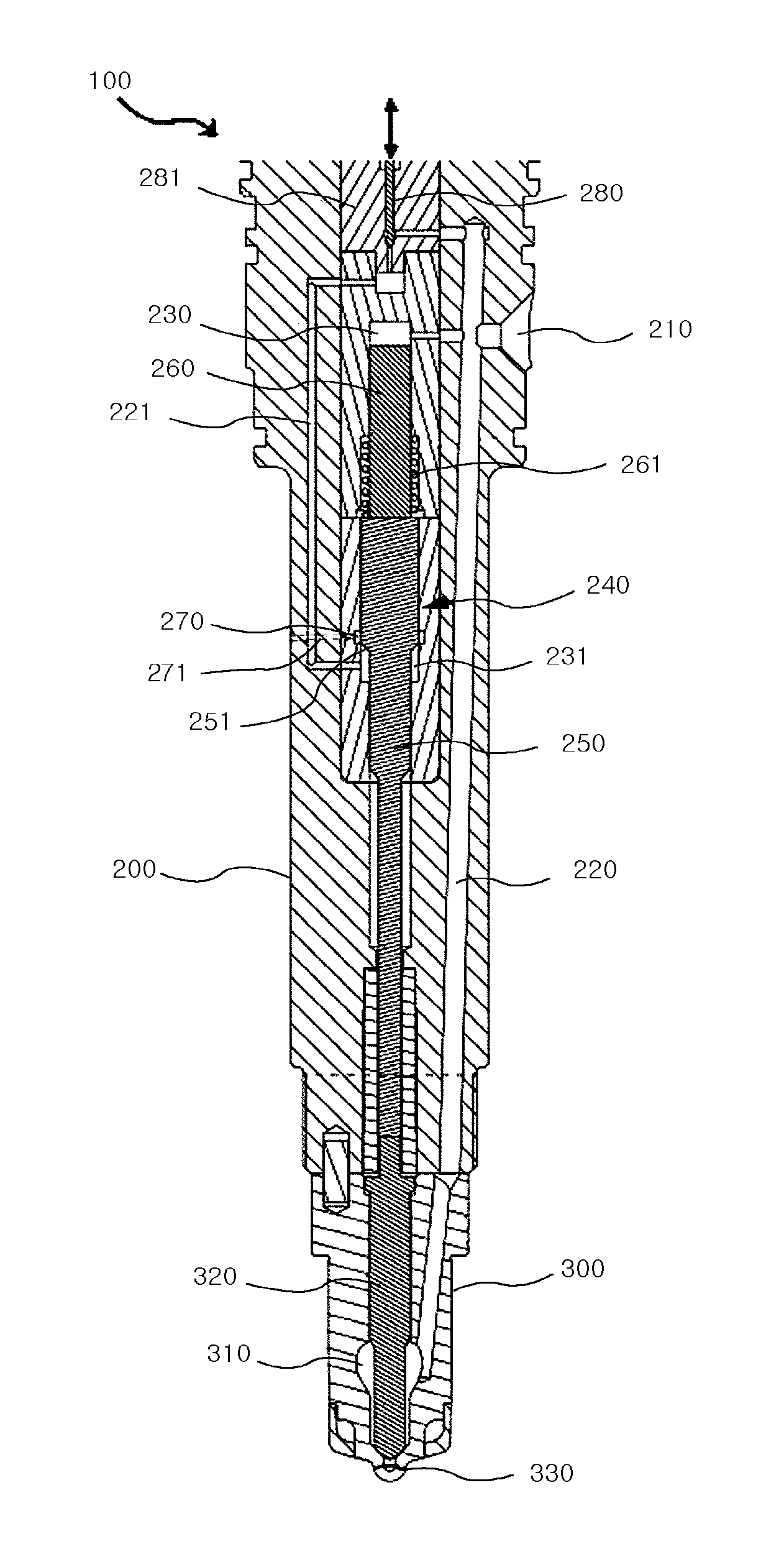
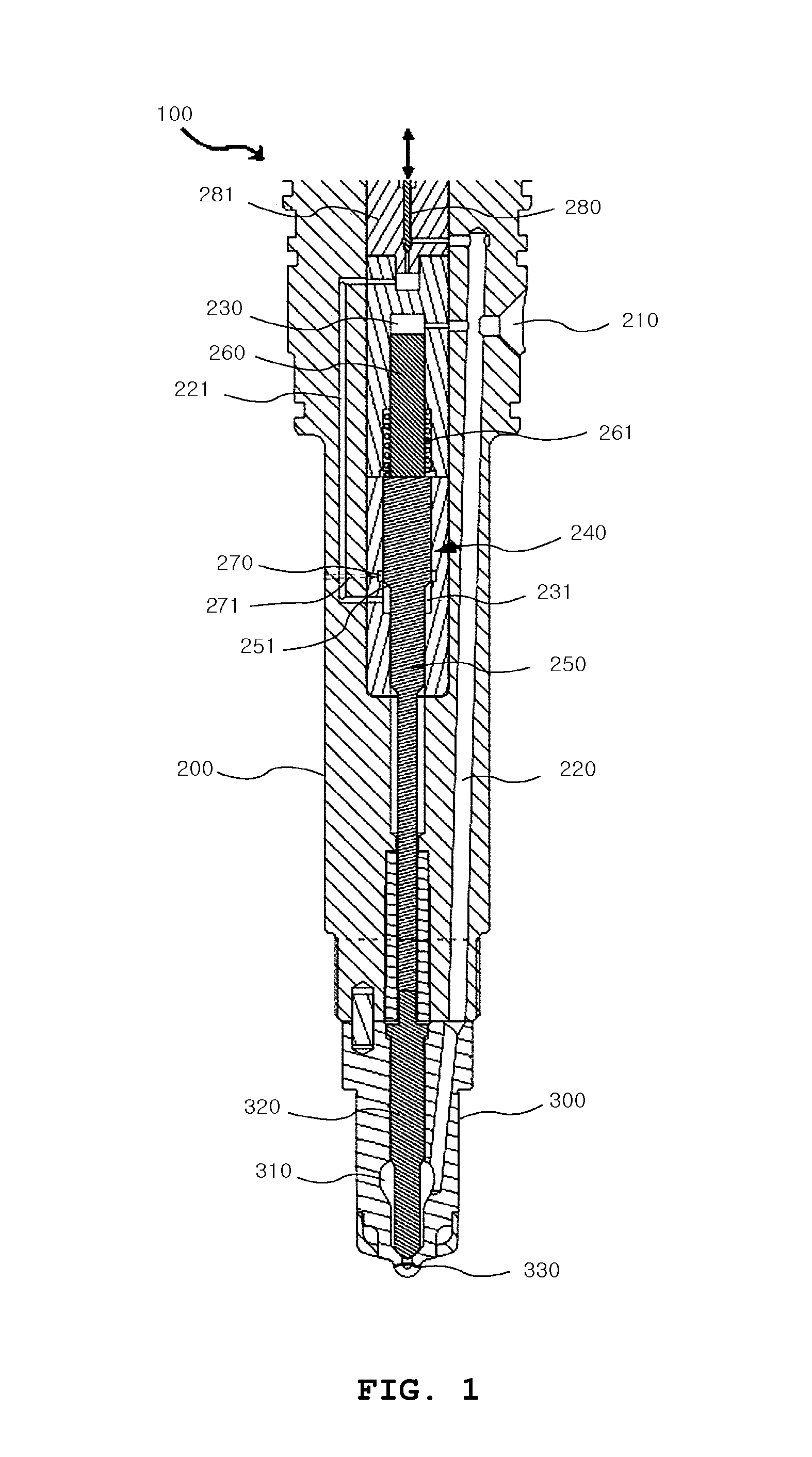
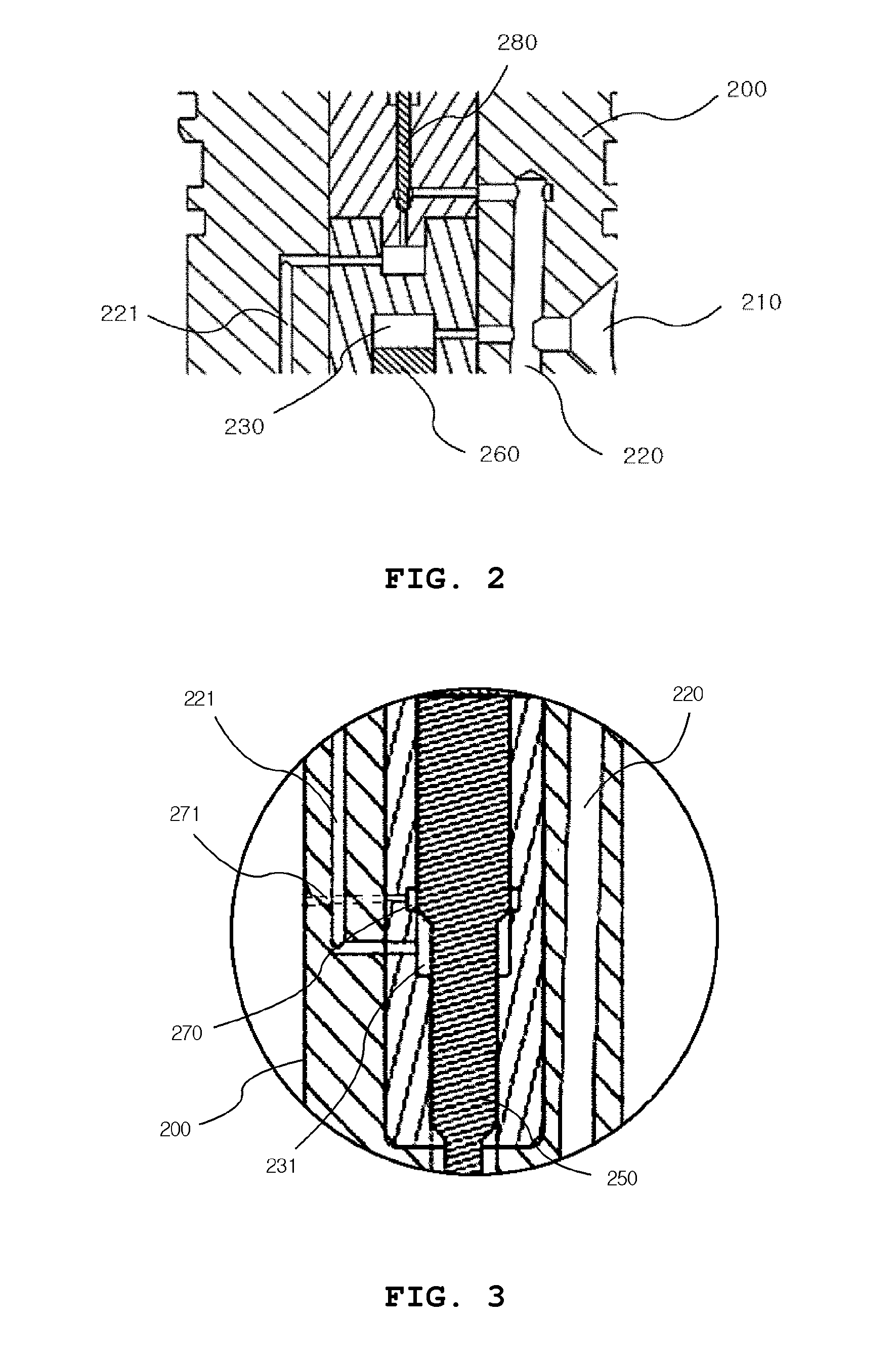
[0030]In the present invention, since the spindle 250 and the pressure piston 350 are separately provided, it is easy to adjust the intervals from the spindle 250 and the pressure piston 260 which require precision machining to the inner circumference of the valve body 200, and thus fabrication cost for the valve is reduced.

[0031]That is, the interval between the spindle 250 and the inner circumference of the valve body 200 and the interval between the pressure piston 260 and the inner circumference of the valve body 200 must be precisely machined to a very small size in order to prevent high-pressure fuel that fills the inside of the upper pressure chamber 230 and the lower pressure chamber 231 from leaking through the intervals. When the spindle 250 and the pressure piston 260 are formed integrally, machining is difficult since one part has a large number of surfaces that must be precisely machined. In contrast, the first embodiment of the present invention is designed such that t...

second embodiment

[0048]As shown in the figures, the fuel injection valve 100 according to the present invention includes a valve body 200, a nozzle part 300, a needle driving part 240, an upper pressure chamber 230, a lower pressure chamber 231, a second flow path 221, a control needle 280, a control chamber 270 and a control orifice 271. The valve body 200 has defined therein a first flow path 220 along which fuel is fed through a fuel supply port 210, and has a control valve housing 281 in the upper portion thereof. The nozzle part 300 is coupled to the lower portion of the valve body 200, and has defined therein a nozzle chamber 310 which is filled with fuel that is supplied via the first flow path 220 so that a needle 320 disposed therein is pressed upward, whereby the needle 320 is lifted up so that fuel is injected toward a nozzle hole 330. The needle driving part 240 is disposed inside the valve body 200, and drives the needle 320 of the nozzle part 300. The upper pressure chamber 230 is form...


PUM


Abstract

An electronically controlled fuel injection valve can control the time to inject fuel and the amount of fuel to be injected in response to a control signal independently from the operating condition of an engine unlike a traditional mechanical fuel injection valve. The electronically controlled fuel injection valve employs a control method for fuel injection that increases the force of lifting up a cutoff needle of an injection controller by delivering high-pressure fuel to a lower pressure chamber via a control needle, thereby rapidly controlling fuel injection, has a simple structure making it easy to assemble, replace and precisely machine parts, and has a simple flow path structure which facilitates fabrication.

Description

TECHNICAL FIELD[0001]The present invention relates, in general, to an electronically controlled fuel injection valve and, more particularly, to an electronically controlled fuel injection valve which can independently control the time to inject fuel and the amount of fuel to be injected in response to a control signal sent from the operating condition of an engine, and when fuel is not injected, prevent a nozzle part from being constantly subjected to high pressure due to the nozzle part being not supplied with fuel.BACKGROUND ART[0002]In response to the development of electronic control technologies, it is the rapidly-growing trend to electronically control engines. Fuel injection methods using a common rail are being widely applied to electronically controlled engines since fuel injection can be performed under high pressure even with a low load and can be easily performed in response to a control signal.[0003]A variety of research and development is being performed on electronica...

Claims


Application Information

Patent Timeline
IPC IPC(8): F02D41/38
CPCF02D41/38F02M61/10F02M63/001F02M2200/50F02M47/02F02M47/027F02M61/205F02D41/401F02M61/20
Inventor KIM, DONG-HUNRYU, SEUNG-HYUPPARK, TAE-HYUNG
Owner HYUNDAI HEAVY IND CO LTD
Why Eureka
Try Eureka