Accumulating fuel injection apparatus

a fuel injection apparatus and accumulator technology, applied in the direction of fuel injecting pumps, machines/engines, electric control, etc., can solve the problems of increasing smoke, inability to use this injector, and not achieving atomization of fuel, so as to reduce the fuel pressure, increase the opening area, and reduce the effect of fuel pressur

Inactive Publication Date: 2002-04-09
ISUZU MOTORS LTD +1
View PDF21 Cites 15 Cited by
  • Summary
  • Abstract
  • Description
  • Claims
  • Application Information

AI Technical Summary

Benefits of technology

When the lift of the needle valve in the accumulating fuel injection apparatus and an engine load are set correlative, the fuel injection rate in a low-load condition can be set low by reducing the opening area of the discharge passage, and that in a high-load condition can be set high by increasing the opening area of the discharge passage.
When the fuel passage, which extends to the injection ports formed at a lower end portion of the injection nozzle, in the accumulator fuel injection apparatus has a flow passage resistance high enough to lower the fuel pressure when a fuel flow exists, a force working on the needle at the lower end portion of the needle valve to lift the needle valve can be reduced at such time that equal fuel pressure is applied to the balancing chamber and injection nozzle by closing the discharge port with the solenoid valve deenergized. This enables the closing of the needle valve to be done reliably.
When a return spring urging the needle valve in the closing direction thereof is provided between the needle valve and casing in this accumulating fuel injection apparatus, the needle valve receives, when the discharge port is closed by deenergizing the solenoid valve, a high fuel pressure occurring momentarily in the balancing chamber, a fuel pressure in the fuel storage chamber and a fuel pressure occurring on the seat in accordance with the respective pressure receiving surface area. Even when a difference between a force based on a fuel pressure and working in the valve closing direction and a force based on the fuel pressure and working in the valve opening direction is small, so that a sufficiently large valve closing force cannot be obtained, the needle valve can be closed reliably since the return spring urges the needle valve constantly in the valve closing direction. When the discharge passage is opened by energizing the solenoid valve, the fuel is discharged from the balancing chamber whether the needle valve is half lifted or fully lifted. Therefore, the pressure in the balancing chamber lowers, and the injection ports are opened by the needle valve. Owing to the positive urging force in the valve closing direction of the return spring, a speedy valve closing action of the needle valve can be obtained, and the after-dripping of the fuel can be prevented.

Problems solved by technology

When an initial injection rate is high, combustion noise and NOx occur.
Consequently, the atomization of the fuel is not attained, and smoke increases.
Therefore, it is impossible to use this injector in combination with the injectors of the first and second conventional examples in which the half lift condition of the needle valve cannot be controlled.
However, in the fourth and fifth conventional examples, the half lifted state of the needle valve cannot be retained, though the half lifted state can be temporarily obtained.
Moreover, when such a half lifting means is used, the lift of the needle valve scatters due to the influence of the actual fuel pressure, so that it is difficult to precisely control the half lifted state of the needle valve.
Therefore, a high-performance solenoid magnetic valve is required, and this causes the manufacturing cost to increase.

Method used


Image

  • Accumulating fuel injection apparatus
  • Accumulating fuel injection apparatus
  • Accumulating fuel injection apparatus

Examples


first embodiment

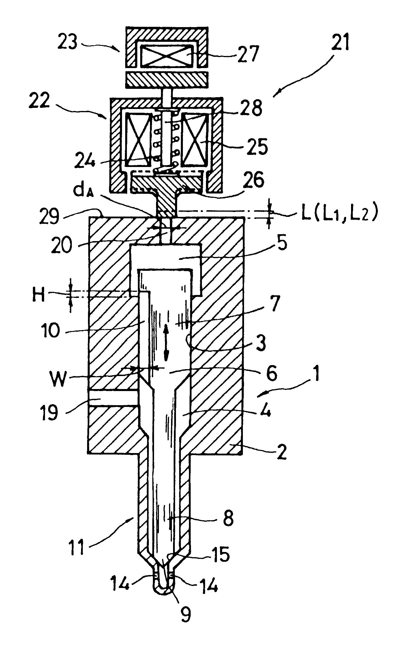
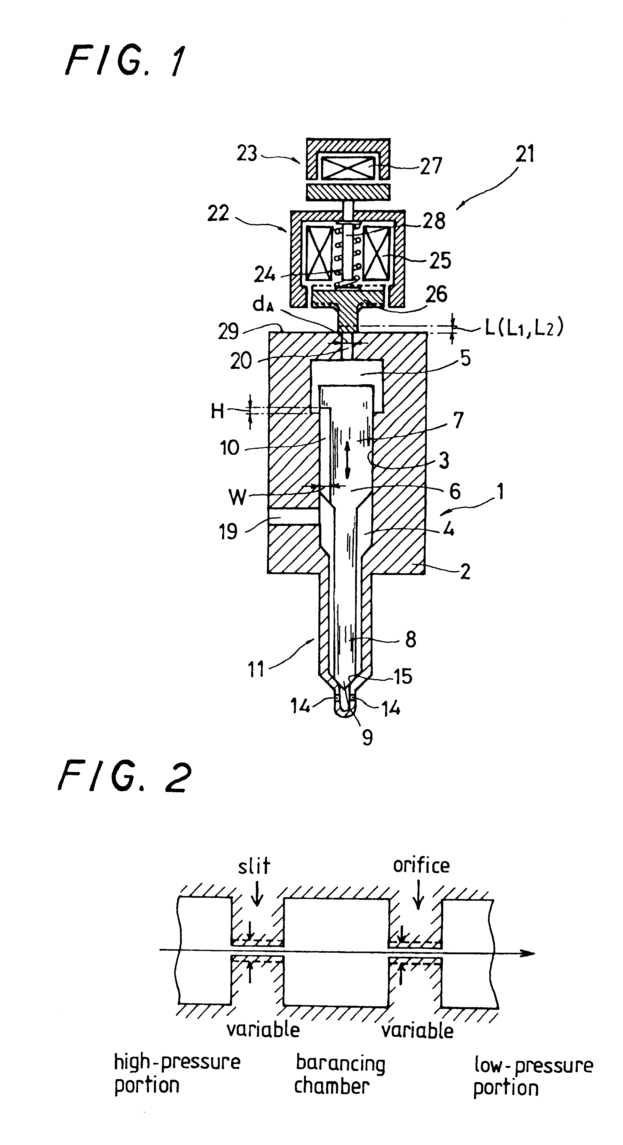
The embodiments of the accumulating fuel injection apparatus according to the present invention will now be described with reference to the drawings. the accumulating fuel injection apparatus according to the present invention will now be described with reference to FIGS. 1 and 2.

As shown in FIG. 1, a casing 2 for an injector 1 is provided therein with a guide bore 3, a fuel storage chamber 4, and a control volume, i.e. a balancing chamber 5. A needle valve 6 is provided slidably in the guide bore 3. The needle valve 6 comprises a larger-diameter portion 7 fitted slidably in the guide bore 3, and a smaller-diameter portion 8 made integral with the larger-diameter portion 7. The larger-diameter portion 7 of the needle valve 6 is provided with a slit 10 communicating the balancing chamber 5 and fuel storage chamber 4 with each other and extending axially. The slit 10 faces the interior of the balancing chamber 5 with the needle valve closed, with an opening area corresponding to a hei...

third embodiment

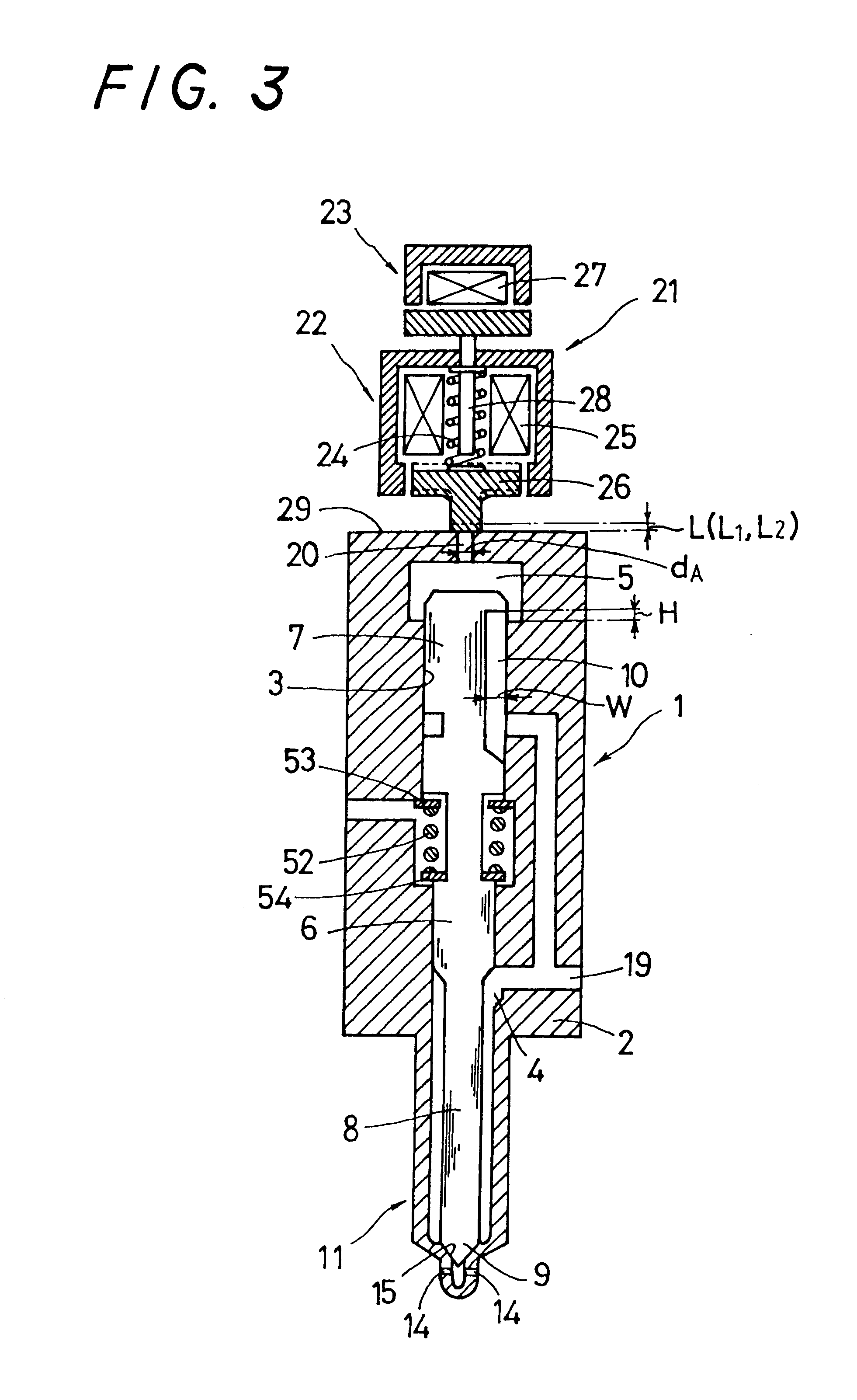
The third embodiment shown in FIG. 4 of the accumulating fuel injection apparatus according to the present invention is provided with a restriction 57 in a fuel supply passage extending from a fuel supply port 19 to an injection nozzle 11, i.e. an annular supply passage formed between a smaller-diameter portion of a needle valve and the portion of an inner surface of a casing which is around the smaller-diameter portion. Owing to this arrangement, when a fuel flows in the fuel supply passage extending from the fuel supply port 19 to the injection nozzle 11, a pressure drop occurs in the fuel in the restriction 57, and the resultant pressure works on a seat 15, so that a force imparted to a needle valve 6 in the valve opening direction becomes smaller. Therefore, when the fuel pressure in a balancing chamber 5 decreases momentarily by an operation of a valve 22, the needle valve 6 can be closed reliably on the basis of a differential pressure working thereon. Since the constituent el...


PUM


Abstract

This accumulating fuel injection apparatus is provided with a needle valve 6 adapted to open and close an injection nozzle 11 having injection ports 14 in a lower end portion thereof, a balancing chamber 5 formed in a casing 2 so as to apply a fuel pressure to a head portion of the needle valve 6, a supply passage including a slit 10 and used for supplying a fuel from a fuel supply port 19 to the balancing chamber 5, a discharge passage 20 comprising an orifice for discharging the fuel from the balancing chamber 5, and a solenoid valve 22 adapted to open and close the discharge passage 20, the lift of a valve disc 26 of the solenoid valve 22 is controlled by a lift control means comprising a stopper 28 the position of which is controlled by a lift control mechanism 23. The opening area of the discharge passage 20 comprising an orifice increases and decreases in accordance with the lift of the valve disc 26, and the lift of the needle valve 6 is determined so that the opening area of the slit 10 facing the interior of the balancing chamber 5 increases and decreases correspondingly to the flow rate of the fuel passing through the discharge passage 20, the degree of opening of the injection nozzle 11 increasing and decreasing accordingly.

Description

TECHNICAL FIELDThis invention relates to an accumulator fuel injection apparatus applied to internal combustion engines, such as a diesel engine.BACKGROUND ARTThe conventional fuel injection apparatuses for multi-cylinder engines include an apparatus of a fuel injection system (electronically controlled fuel injection system) in which the controlling of an injection rate and injection time is done by an electronic circuit, an apparatus of a common injection system (common-rail injection system) in which a fuel is distributed from an injection pump to combustion chambers through a common passage, and an apparatus of a pressure storage type injection system (accumulator injection system) in which a fuel is distributed from an injection pump to combustion chambers through a common passage and an accumulator. Since the fuel injection apparatuses themselves of these systems are not provided with an accumulator in which the fuel from an injection pump is temporarily stored, the supplying ...

Claims


Application Information

Patent Timeline
Patent Type & Authority Patents(United States)
IPC IPC(8): F02M61/00F02M61/16F02M59/00F02M59/46F02M61/18F02M61/04F02M61/06F02M45/08F02M45/12F02M47/02F02M45/00F02M63/00
CPCF02M45/08F02M45/12F02M47/027F02M61/042F02M61/06F02M61/161F02M61/1806F02M63/0017F02M63/0019F02M63/0056F02M63/0063F02M63/0066F02M63/0068F02M2200/21F02M2547/008
Inventor FUSEYA, TSUTOMU
Owner ISUZU MOTORS LTD
Why Eureka
Try Eureka