Internal combustion engine with variable valve control device

a control device and internal combustion engine technology, applied in the direction of electrical control, two-way working system, instruments, etc., can solve the problem that the control measures of fuel injection timing in accordance with the lift degree of the intake valve have been given little though

Inactive Publication Date: 2003-08-28
NISSAN MOTOR CO LTD
View PDF4 Cites 4 Cited by
  • Summary
  • Abstract
  • Description
  • Claims
  • Application Information

AI Technical Summary

Benefits of technology

0006] Accordingly, it is an object of the present invention to provide an internal combustion eng...

Problems solved by technology

However, hitherto, even by the above-mentioned publications, assured measures for controlling a fue...

Method used


Image

  • Internal combustion engine with variable valve control device
  • Internal combustion engine with variable valve control device
  • Internal combustion engine with variable valve control device

Examples


first embodiment

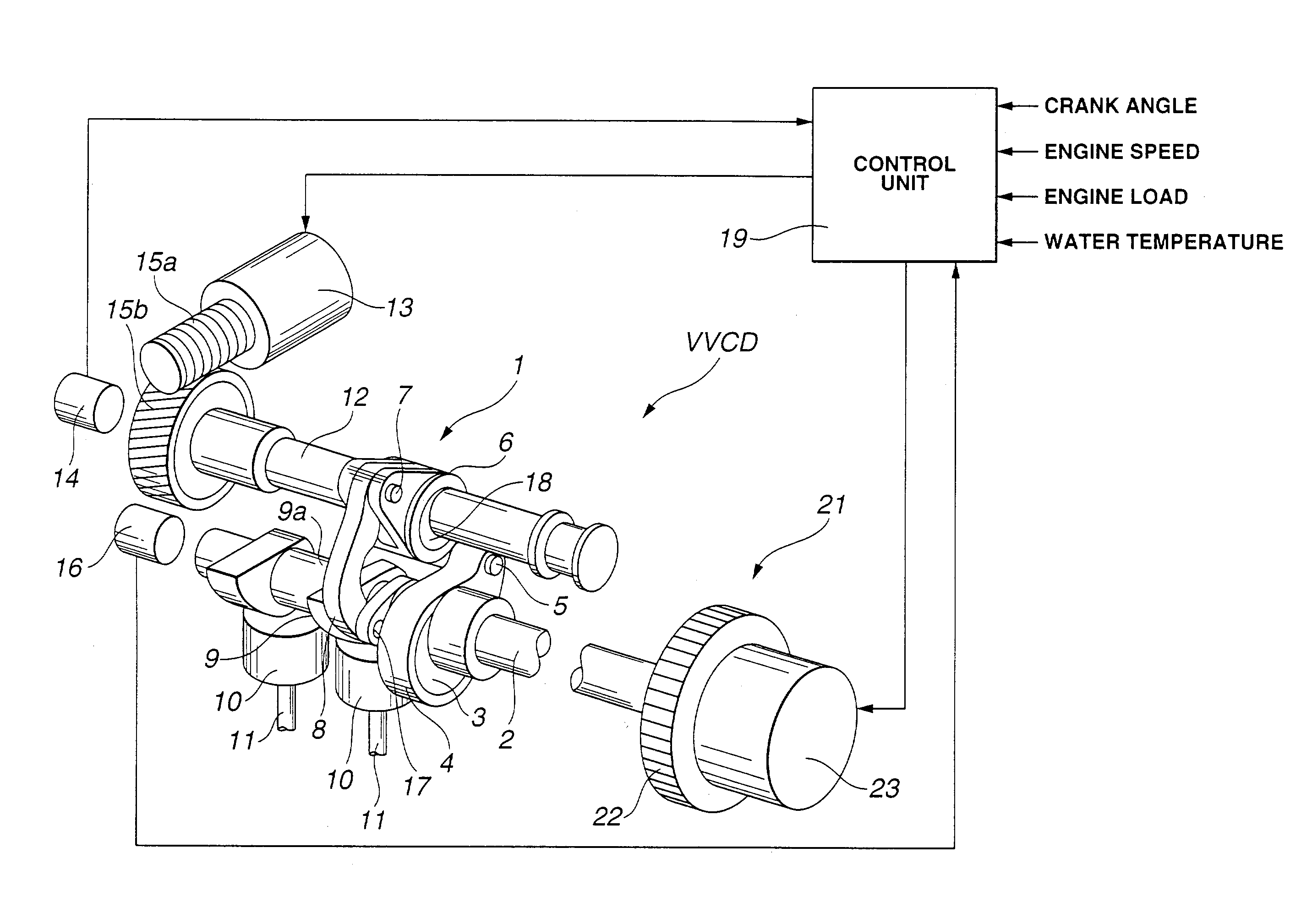
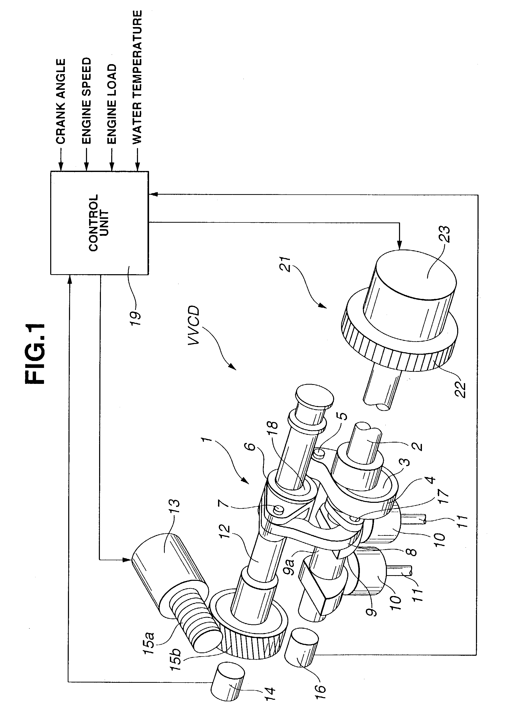
[0064] Accordingly, in the present invention, as is seen from FIG. 7, the first fuel injection mode "FIAIVO" and the second fuel injection mode "FIBIVO" are controlled in accordance with the lift degree of intake valve 11. That is, when the lift degree is smaller than a predetermined value, the first fuel injection mode "FIAIVO" is carried out, and when the lift degree exceeds the predetermined value, the second fuel injection mode "FIBIVO" is carried out. It is to be noted that the lift degree of intake valve 11 is detected based on a rotation angle of control shaft 12 (see FIG. 1) detected by rotation angle sensor 14.

[0065] In the following, control of the fuel injection timing carried out in the first embodiment will be described with reference to the flowchart of FIG. 8.

[0066] At step S101, a rotation angle "RACS" of control shaft 12 is read. At step S102, judgment is carried out as to whether the rotation angle "RACS" is smaller than a predetermined value "X" or not. If YES, th...

second embodiment

[0070] In FIGS. 10 and 11, there is depicted the present invention.

[0071] In this second embodiment, an engine speed is additionally used as a parameter for controlling the fuel injection timing, more specifically, for controlling the switching timing between the two fuel injection modes "FIAIVO" and "FIBIVO".

[0072] As is seen from FIG. 10, in this second embodiment, the lift degree of intake valve 11 and the engine speed are used as parameters for determining the switching timing. That is, basically, below a given lift degree of intake valve 11, the first fuel injection mode "FIAIVO" is carried out, and above the given lift degree, the second fuel injection mode "FIBIVO" is carried out. While, the switching point at which the first fuel injection mode "FIAIVO" changes to the second fuel injection mode "FIBIVO" increases with increase of the engine speed.

[0073] This is because of a phenomenon wherein with increase of the engine speed, the intake air speed in intake port is increased...

third embodiment

[0078] In FIGS. 12 and 13, there is depicted the present invention.

[0079] In this third embodiment, an advanced degree of the operation phase of intake valve is additionally used as a parameter for controlling the fuel injection timing, more specifically, for controlling the switching timing between the two injection modes "FIAIVO" and "FIBIVO".

[0080] As is seen from FIG. 12, in this third embodiment, basically, below a given lift degree of intake valve 11, the first fuel injection mode "FIAIVO" is carried out, and above the given lift degree, the second fuel injection mode "FIBIVO" is carried out.

[0081] Furthermore, in the mode of the first fuel injection mode "FIAIVO", in accordance with the phase control value and the lift degree of intake valve 11, the fuel injection timing is controlled to select a first timing mode at which the opening movement of intake valve 11 starts or a second timing mode at which the piston takes its upper dead center (UDC) in intake stroke. As is seen f...


PUM


Abstract

An internal combustion engine comprises a variable valve control device that varies a lift degree of an intake valve, an air intake passage led to an intake port of the engine that is incorporated with the intake valve and a fuel injection valve arranged to inject fuel into the intake port. The fuel injection valve has a first injection mode wherein each fuel injection shot is entirely carried out during opening period of the intake valve and a second injection mode wherein each fuel injection shot entirely finishes prior to opening action of the intake valve. A control unit is further employed by the engine, which allows the fuel injection valve to select one of the first and second injection modes in accordance with the lift degree of intake valve effected by the variable valve control device.

Description

BACKGROUND OF INVENTION[0001] 1. Field of Invention[0002] The present invention relates in general to fuel injection type internal combustion engines and more particularly to the internal combustion engines of a type that is equipped with a variable valve control device.[0003] 2. Description of Related Art[0004] Hitherto, various types of internal combustion engines of the above-mentioned type have been proposed and put into practical use particularly in the field of wheeled motor vehicles. Some of them are disclosed in Laid-open Japanese Patent Applications (Tokkai) 2001-221083 and 8-260923. In the publication of 2001-221083, a base operation is so made that fuel injection finishes before opening of an intake valve, and when a valve overlapping becomes to a marked value due to changing of the phase of a lift degree / working angle of an intake valve, retarding of the fuel injection timing is carried out. In the publication 8-260923, there is shown a variable valve control device that...

Claims


Application Information

Patent Timeline
IPC IPC(8): F01L13/00F02D13/02G06F17/30F02D41/36H04N7/173H04N21/2668H04N21/84
CPCF01L1/022F01L1/024F01L13/0026F01L2013/0073Y02T10/18F02D13/0215F02D41/345F02D2041/001Y02T10/44F01L2800/00Y02T10/12Y02T10/40
Inventor SUGIYAMA, TAKANOBUTAKEMURA, SHINICHINOHARA, TSUNEYASU
Owner NISSAN MOTOR CO LTD
Why Eureka
Try Eureka