Excavator wear assembly

a technology for excavators and tooth assemblies, applied in the field of excavators, can solve the problems of increasing the risk of losing a digging point or an entire adaptor/tooth combination, damage and/or further downtime, and imposing twisting or “yaw” loads on such tooth assemblies

Active Publication Date: 2013-12-19
CQMS PTY LTD
View PDF16 Cites 82 Cited by
  • Summary
  • Abstract
  • Description
  • Claims
  • Application Information

AI Technical Summary

Benefits of technology

[0027]wherein the locking member of the retaining assembly is adapted to engage with the flange portion of the locking pin to prevent withdrawal of the locking pin from the retaining assembly when the locking assembly is in a locked position.
[0030]According to a form of the invention, the locking ring has a tab. The tab may be in the form of a flattened portion that is preferably in the form of a segment of the locking ring. The tab preferably corresponds to the flange portion of the locking pin. The tab is preferably located across the inner wall of the locking ring. Preferably the inner wall of the locking ring is chamfered except for the tab. The tab is preferably located approximately 90° from the opening. The tab preferably increases the radial width of the locking ring.
[0046]wherein the tab of the locking member is adapted to engage with the flange portion of the locking pin to prevent withdrawal of the locking pin from the retaining assembly when the lock assembly is in a locked position.
[0052]wherein the locking member is adapted to engage with a flange portion of the locking pin to prevent withdrawal of the locking pin when the locking pin is in a locked position.
[0058]wherein the locking aperture and retaining assembly located in the locking aperture are adapted to receive a locking pin, with the locking member being adapted to deform perpendicular to the longitudinal axis of the locking pin as the locking pin is inserted longitudinally into the retaining assembly and to engage with a flange portion of the locking pin to prevent withdrawal of the locking pin from the locking aperture when the locking pin is in a locked position.
[0065]wherein the locking member is adapted to deform perpendicularly to a longitudinal axis of the locking pin as the locking pin is inserted longitudinally into the retaining assembly and to engage with a flange portion of the locking pin to prevent withdrawal of the locking pin when the locking pin is in a locked position.

Problems solved by technology

As the various components wear, the locking pins can loosen thereby increasing the risk of loss of a digging point or an entire adaptor / tooth combination.
This necessitates considerable downtime to replace the lost wear members and where items such as locking pins are not recovered, these can cause damage and / or further downtime in downstream operations such as ore crushing and the like.
In addition, twisting or “yaw” loads are frequently imposed on such tooth assemblies.
Despite many prior art attempts to improve the mounting of a wear member to a nose of an excavator, most of these proposals suffer from one or more deficiencies.
Because the tongues themselves are unsupported, they possess a limited capacity to resist rotational moment forces.
Because the side tongues are recessed to accommodate the side rail portions, the robustness of the side tongues is somewhat compromised.
This structure is heavily reliant on the locking pin to resist rotational moment forces however it is considered that this configuration may be prone to failure in the rear portion of the adaptor.
While adequate for securing an adaptor to a nose of an excavator support structure, the lock described in this patent is relatively complex in design and operation leading to high costs and labour intensive extraction procedures in the field.
While generally satisfactory for their intended purpose, the abovementioned prior art all suffer from one or more shortcomings or disadvantages in terms of inadequate resistance to rotation of a tooth off a nose or an adaptor under the influence of vertical loads applying a rotational moment to the tooth, a predisposition to premature wear, difficulties in retention of the teeth on noses or adaptors, inadequate locking systems and unduly complicated configurations giving rise to increased fabrication costs.
Furthermore, the prior art all generally rely on lock assemblies that require threaded components.
Thread components in lock assemblies are generally disadvantageous as dirt and fines can infiltrate the threaded assembly thereby causing cementation and resulting in difficulties in removal.

Method used


Image

  • Excavator wear assembly
  • Excavator wear assembly
  • Excavator wear assembly

Examples


Embodiment Construction

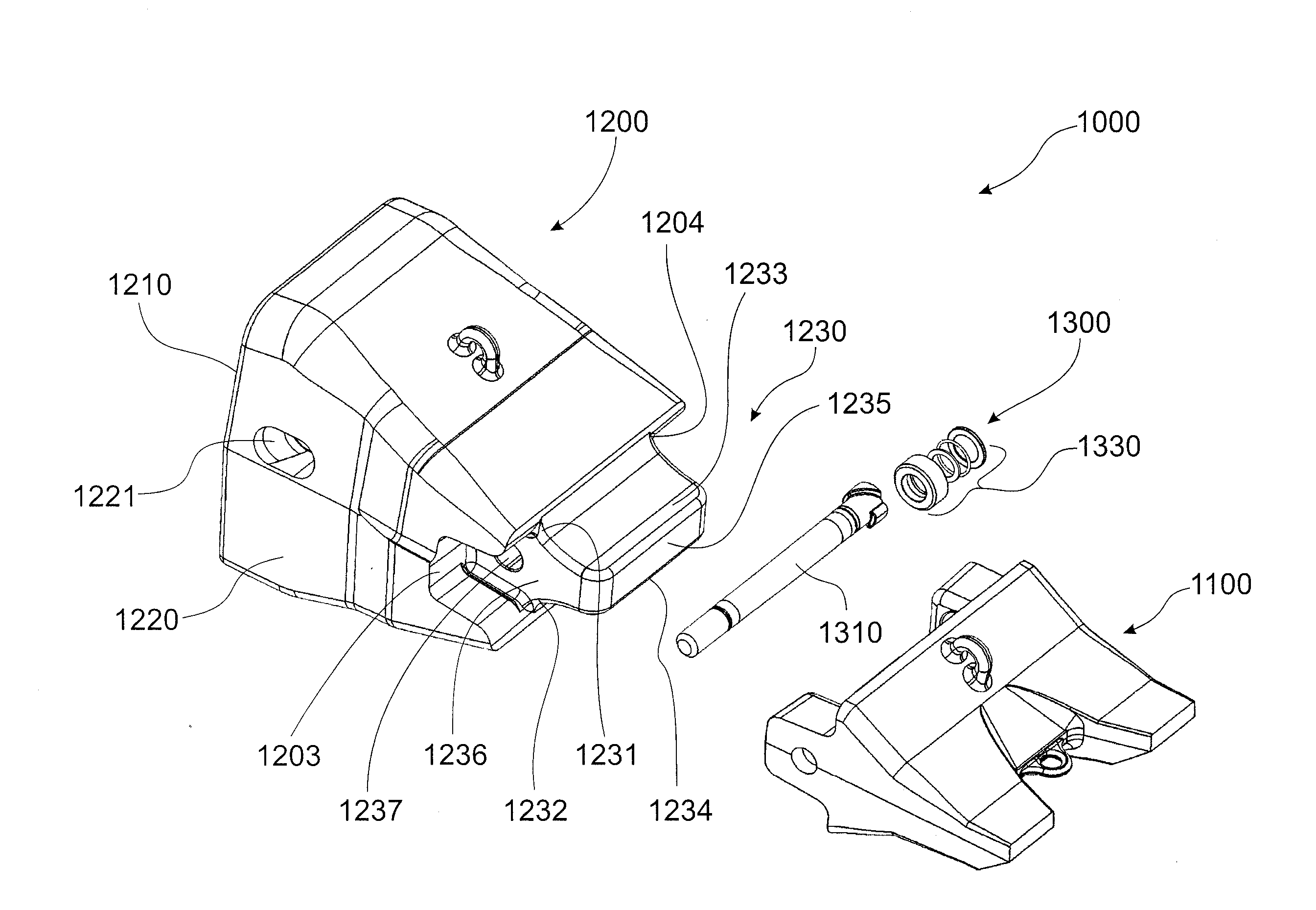
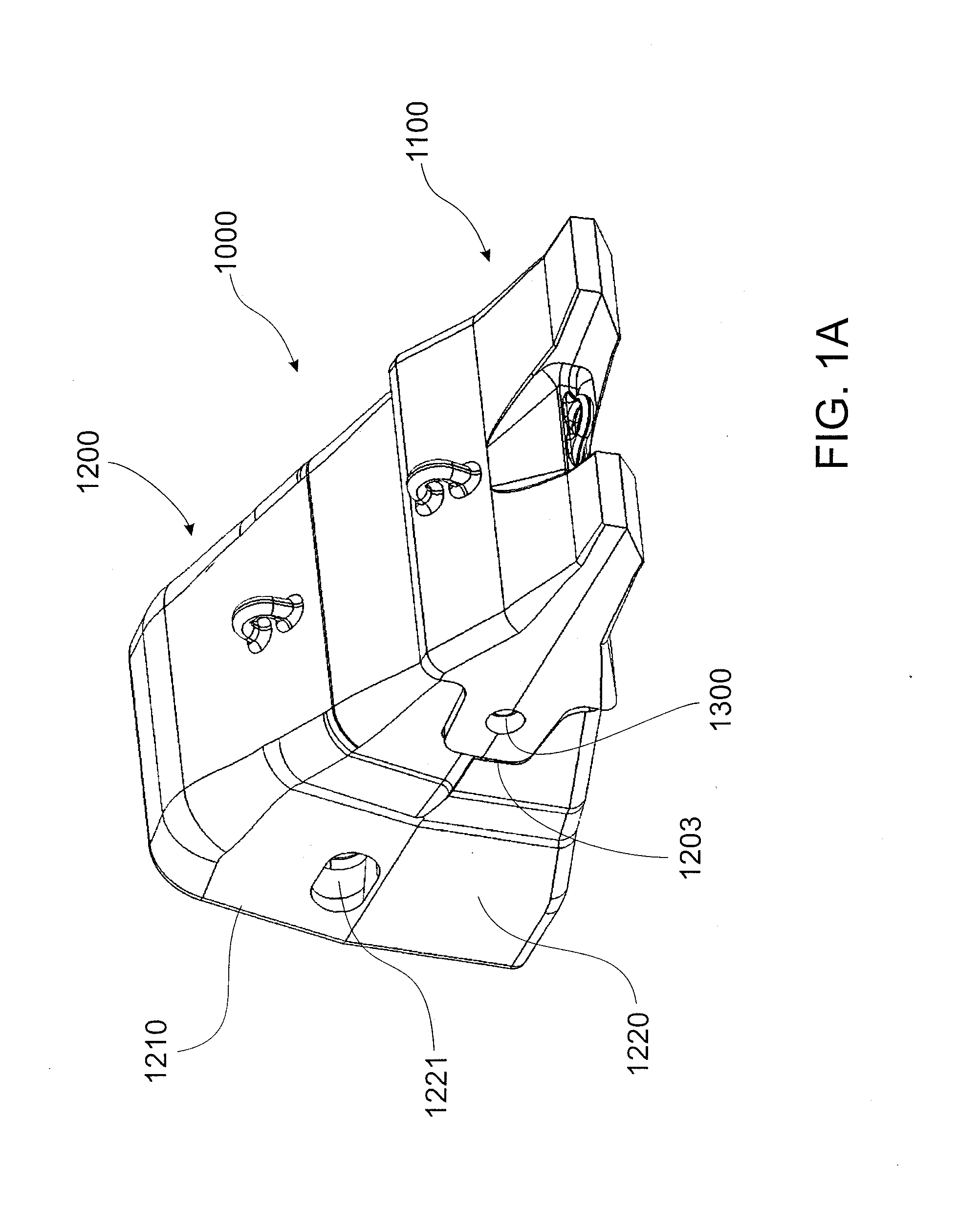
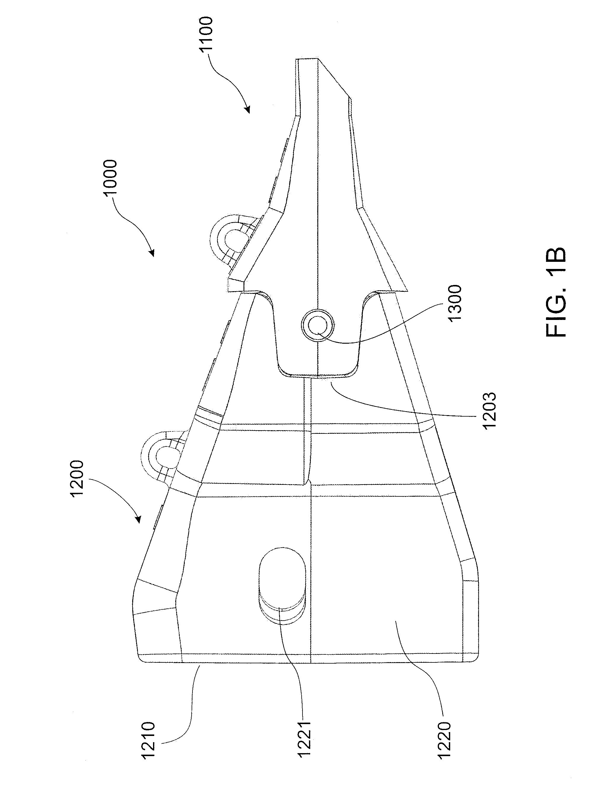
[0112]The excavator wear assembly and lock assembly are described with reference to an excavator wear member in the form of a tooth releasably secured to an adaptor. The adaptor is in turn secured to a nose of an excavator bucket or the like. A skilled addressee will appreciate that the invention may be employed to releasably secure an adaptor to a nose or a tooth directly to a nose of an excavator bucket lip and the like. Furthermore, the lock assembly may be utilised in other applications such as a retaining pin for components in dragline excavator rigging and the like.

[0113]FIG. 1A shows a perspective view of an excavator wear assembly 1000 according to an embodiment of the invention in the locked position. FIG. 1B shows a side elevation view of the excavator wear assembly 1000. FIG. 1C shows an exploded perspective view of the excavator wear assembly 1000 which is effectively in an unlocked position. Excavator wear assembly 1000 comprises a wear member in the form of a tooth 110...


PUM

PropertyMeasurementUnit
resilientaaaaaaaaaa
radial widthaaaaaaaaaa
circumferenceaaaaaaaaaa

Abstract

A lock assembly to lock two members together, typically an excavator wear member, such as a tooth, on to an adaptor. The lock assembly has a locking pin with a flange portion and a retaining assembly that receives the locking pin. The retaining assembly includes a locking member, in the form of a locking ring, which deforms radially when a tapered portion of the locking pin is inserted into the retaining assembly. In the locked position, the locking ring engages with the flange portion of the locking pin to prevent withdrawal of the locking pin from the retaining assembly.

Description

FIELD OF THE INVENTION[0001]The invention relates to an excavator wear assembly. In particular, although not exclusively, the invention relates to an assembly for releasably securing an excavator tooth to a nose of an excavator.BACKGROUND TO THE INVENTION[0002]Excavator tooth assemblies mounted to the digging edge of excavator buckets and the like generally comprise a replaceable digging tooth, an adaptor body and an adaptor nose which is secured by welding or the like to the digging edge of a bucket or the like. The tooth generally has a socket-like recess at its rear end to receivably locate a front spigot portion of the adaptor nose and a removable locking pin is generally employed to releasably secure the tooth on the adaptor.[0003]In use, excavator teeth are subjected to extensive load forces along a longitudinal axis of a tooth as well as in vertical and transverse directions. A snug fit is required between the digging point and the front portion of the adaptor and also betwee...

Claims


Application Information

Patent Timeline
Patent Type & Authority Applications(United States)
IPC IPC(8): E02F9/28
CPCE02F9/2833E02F9/2825E02F9/2841Y10T29/49947
Inventor WALLIS, DOUGLASGUIMARAES, MIGUELLILLEY, BRUCEKIRSCH, JOSUA
Owner CQMS PTY LTD
Why Eureka
Try Eureka