Method for producing a functional layer of a building shell, and building shell and functional layer

a technology of building shells and functional layers, applied in the direction of superimposed coating processes, liquid/solution decomposition chemical coatings, manufacturing tools, etc., can solve the problems of unacceptably high levels of melt water or condensation water formation, unacceptably wet subjacent layers, and damage to functional layers by mechanical, chemical and physical stresses

Active Publication Date: 2013-12-19
EWALD DORKEN
View PDF3 Cites 2 Cited by
  • Summary
  • Abstract
  • Description
  • Claims
  • Application Information

AI Technical Summary

Benefits of technology

[0010]The object of this invention is to make available a method and a building shell of the above-mentioned type, whereby a functional layer can also be applied in a simple way in a roof square.
[0011]Another object of this invention is to make available a functional layer for a building shell or a method for the production of a functional layer, whereby in a simple way, a matching of the functional layer to specific details of the building shell is possible, and at the same time the necessary sealing of the functional layer is ensured.
[0014]As a result, a method is provided by the invention, with which it is possible, in a simple way, to apply a tight functional layer quickly and without damage to the outside of a sheathing that forms the bottom or base of a roof square and that, moreover, meets all construction requirements. Moreover, the invention thus provides a material or a method, whereby—regardless of the composition of the base and the type of geometric requirement—the detail of the building or the building shell in question can be equipped quickly and easily with a functional layer, which meets all construction requirements. The foil that is applied by spraying and / or painting, which is referred to below as “spray foil” for the sake of simplicity, but is not limited to spraying, but rather can also be painted, offers the significant advantage that it can be applied very much faster and easier than a structural composite foil that is inserted into the roof square that can optionally be assigned to, and moreover, fastened there accordingly. In this case, the spray foil is preferably applied as the inner or bottommost layer, i.e., indirectly or directly, on the external roof system. By a corresponding selection of material of the spray foil, it can be ensured that the latter adheres securely to the outside of the sheathing, i.e., special fastening means are not necessary.
[0036]Depending on the composition of the base and / or the width of the gap to be repaired, it is also possible to work with a support structure / layer. The latter is used to offset greater roughnesses and porosities or to span gaps. The support structure / layer can be, e.g., a non-woven fabric or cloth. In particular, light non-woven fabrics (10-50 g / m2) made of polypropylene or polyester can be used, since the latter are inexpensive and flexible and offer a good base for coating with the spray foil.
[0046]The drying time at 20° C. and 50% relative humidity is preferably <5 hours, so that a continuation of the procedure is possible within a reasonable period after applying the spray foil. The spray foil is then surface-dry and can withstand small loads. The drying time is preferably less than two hours and more preferably <1 hour, whereby an open time of >5 minutes, preferably between 6 and 20 minutes, can be useful to make corrections possible.
[0111]Although a connection between the additional foil strips provided on the top of the rafter or the additional foil with the lower spray foil is not absolutely necessary, nevertheless an excessive coating in this area, i.e., a cover in the edge area with a few centimeters, is preferably provided, since in this respect, the air-tightness can be better ensured.

Problems solved by technology

As a result, the subjacent layers can become unacceptably soaked, soiled and / or damaged.
Internal factors are, e.g., water vapor convection or diffusion, which can result in unacceptably high levels of melt water or condensation water formation.
Also, when installing a structural composite foil, damages of the functional layer by mechanical, chemical and physical stresses can occur.
Altogether, it is thus difficult to produce the necessary water-tightness and air-tightness of the structural composite foil.
The disadvantage of this method is that structural composite foils can be matched to or connected in a time-consuming and difficult way with aids, e.g., nails, staples, adhesive tapes, e.g., with geometrically demanding and / or poorly available details.
Special difficulties arise even when installing a functional layer in the region of the roof squares.
The arrangement of a structural composite foil in the roof square and the connection to the sheathing is often difficult and time-consuming.

Method used


Image

  • Method for producing a functional layer of a building shell, and building shell and functional layer
  • Method for producing a functional layer of a building shell, and building shell and functional layer
  • Method for producing a functional layer of a building shell, and building shell and functional layer

Examples


Embodiment Construction

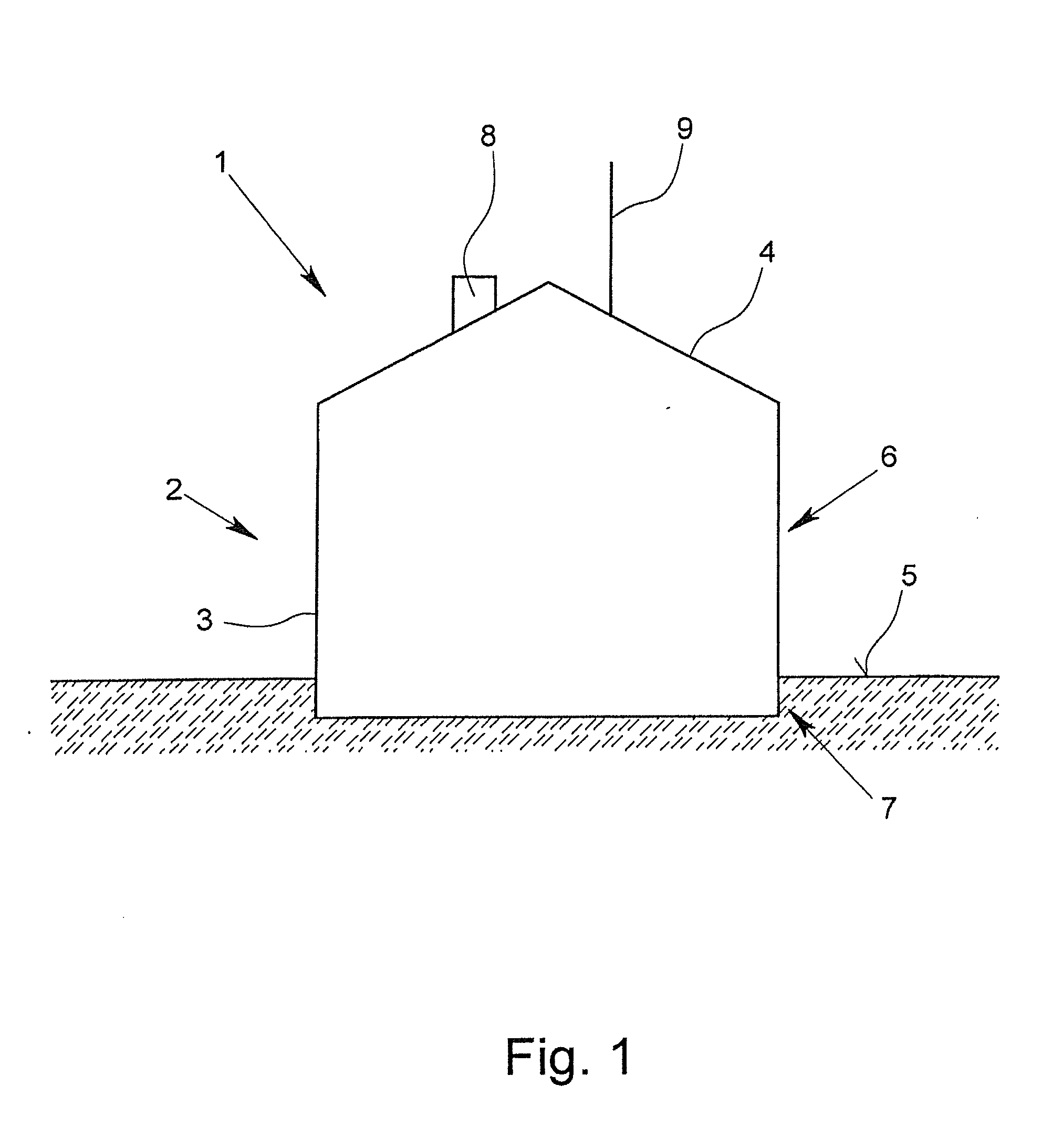
[0183]In FIG. 1, a building 1 with a building shell 2, is depicted diagrammatically. The building shell 2 has a façade 3 and a roof 4. In this case, the façade 3 is divided into a non-ground-based façade area 6 that is located above the ground 5 and into a ground-based façade area 7 that is below the surface of the ground 5. In the area of the roof 4, a chimney 8 and an antenna 9 are present.

[0184]The building shell 2 is provided with a functional layer that is not shown in FIG. 1 and that can cover a full surface or a partial surface in the area of the façade 3 and / or the roof 4. In this case, it is understood that areas in which doors, windows or else the chimney 8 or the antenna 9 or else other details are located are excluded therefrom.

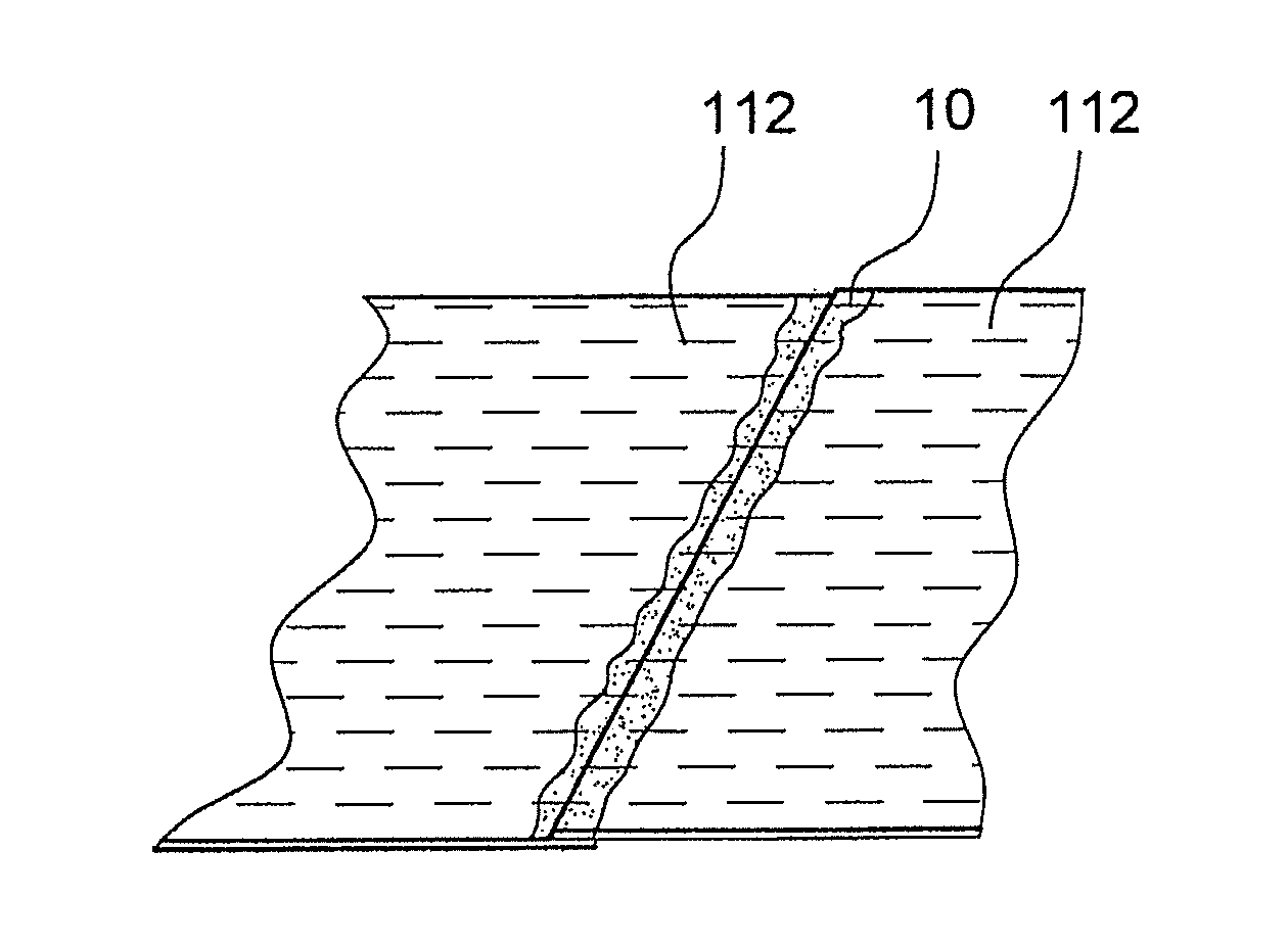
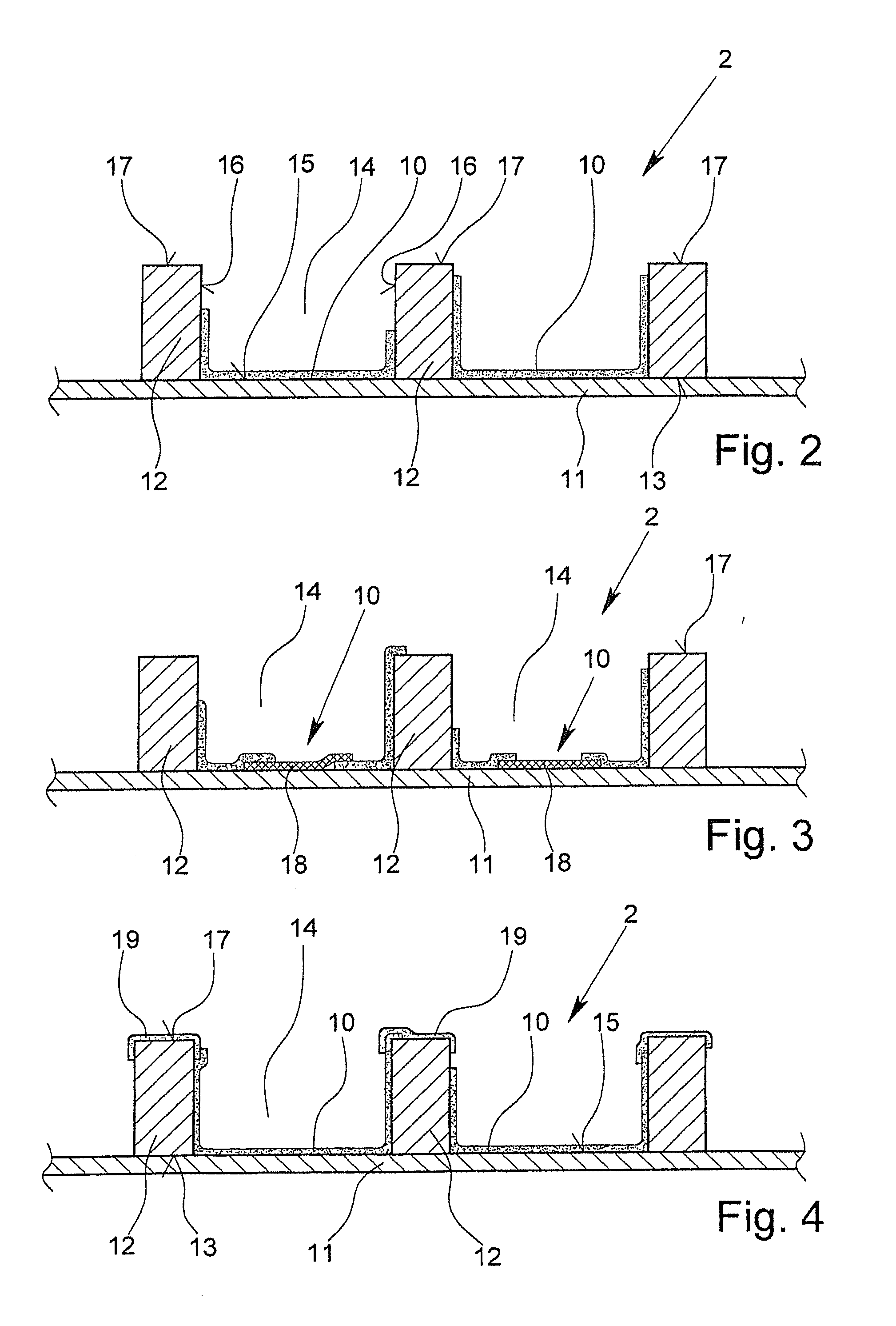
[0185]In FIGS. 2 to 4, a part of a roof system of the building 1 is now depicted. The roof system in this case is also part of the building shell 2, which—in the roof area—has a sheathing 11 on the inside of the building and a large number of raft...


PUM

PropertyMeasurementUnit
temperatureaaaaaaaaaa

Abstract

A functional layer for a building shell, a method for production of the functional layer, and a building shell with the functional layer applied thereto. The building shell has a sheathing on its inside and a large number of rafters with roof bays provided between the rafters and the sheathing. The functional layer is applied at least in some places by painting and / or spraying on the outside of the sheathing, and an air-tight and / or water-tight foil, made especially as a vapor barrier, forms after application.

Description

CROSS REFERENCE TO RELATED APPLICATION[0001]This application is a divisional of co-pending U.S. patent application Ser. No. 13 / 260,764.BACKGROUND OF THE INVENTION[0002]1. Field of the Invention[0003]The invention relates to a method for producing a functional layer of a building shell. In addition, this invention relates to a functional shell, produced, in particular, according to the above-mentioned method, as well as a functional layer produced, in particular, according to the above-mentioned method.[0004]2. Description of Related Art[0005]These days, high requirements are set for roofs and façades, i.e., the building shell, because of internal and external factors. External factors are water in liquid form (rain, light snow, melt water, etc.), but also dust, dirt and insects, which penetrate or are driven in through cuts and joints in the cover material. As a result, the subjacent layers can become unacceptably soaked, soiled and / or damaged. Internal factors are, e.g., water vapo...

Claims


Application Information

Patent Timeline
Patent Type & Authority Applications(United States)
IPC IPC(8): E04B1/66
CPCE04B1/665E04B1/66E04D12/00E04D13/147E04D13/1625
Inventor SCHROER, JORNLIPPS, JOCHENMEYER, GEORG
Owner EWALD DORKEN
Why Eureka
Try Eureka