Safety pneumatic tire for the biclycle

a pneumatic tire and safety technology, applied in the direction of tyre beads, without separate inflatable inserts, and with separate inflatable inserts, etc., can solve the problems of escaping through the broken hole of the inner tube, leaking compressed air inside the inner tube, and causing immediate deflation of the tire, and corresponding loss of stability of the bicycl

Inactive Publication Date: 2006-04-13
KUO HSU SHWU +1
View PDF9 Cites 6 Cited by
  • Summary
  • Abstract
  • Description
  • Claims
  • Application Information

AI Technical Summary

Benefits of technology

[0013] The advantages of the invention is to provide a completely closed and sealed chamber between the pneumatic tire and upper bridge of tubeless rim which has no spoke holes except a valve hole. The inflated improved inner tube presses against the improved tire (outer cover) and the tire beads are tightly fixed on the bead seats of the tubeless rim. When the improved inner tube is punctured, the pressurized air escapes from the inner tube but is confined in the closed and sealed chamber between the improved tire and the upper bridge of the tubeless rim. Therefore, pressure is maintained within the improved tire and the bicyclist then is able to continue riding without risk of falling. Also, a further advantage of the invention is that it allows for easy inflation by a manual pump, even a mini manual pump, as compared to the tubeless tire since the process and rate of inflation is not hampered by leakage of compressed air through gaps between the tire beads and the rim bead seats during the inflation process, which is the situation with the tubeless tire. Instead, it is the improved inner tube that is inflated, which is a sealed, closed system that can be easily inflated with any manual pump. So, unlike the tubeless tire, the invention does not require rapid pressurization of the tire to create the necessary seal between the tire beads and bead seats to avoid leakage during the inflation process.
is that it allows for easy inflation by a manual pump, even a mini manual pump, as compared to the tubeless tire since the process and rate of inflation is not hampered by leakage of compressed air through gaps between the tire beads and the rim bead seats during the inflation process, which is the situation with the tubeless tire. Instead, it is the improved inner tube that is inflated, which is a sealed, closed system that can be easily inflated with any manual pump. So, unlike the tubeless tire, the invention does not require rapid pressurization of the tire to create the necessary seal between the tire beads and bead seats to avoid leakage during the inflation process.

Problems solved by technology

The deficiency of the traditional inner tube is that when it is torn or punctured, the compressed air inside the inner tube then leaks through the broken hole of the inner tube and escapes through the rim valve hole and rim spoke openings and the gaps between the tire beads and rim bead seat.
The result is an immediate deflation of the tire and corresponding loss of stability of the bicycle.
The rider's safety in such an event at serious risk.
First, the beads of a traditional tire does not have elastomeric covering so that the contact between the beads of the tire and the rim bead seats is loose which allows compressed air to escape.
Second, the traditional rim of a typical tire assembly has numerous unsealed spoke openings on the central annular channel to accommodate the spokes of the wheel.
Third, the air valve of the traditional inner tube is purposefully not integrated with the rim valve opening so that air between the inner tube and tire may escape as the inner tube is inflated.
Therefore, because above described sealing problems in a typical tire assembly, the volume between the tire and the inner tube is not totally separated from surrounding enviroment and compressed air may leak into the atmosphere of the surrounding enviroment once the inner tube is punctured or torn.
However, the requirement for bicycle tires is to be lightweight, so the structure of the tubeless tire is quite thin, especially at the tire beads.
As a result, the beads of the tubeless tire easily deform, causing a gap between the tire beads and the rim bead seats and giving rise to a sealing problem.
This problem becomes especially apparent when the tubeless tire is inflated with a manual pump since the rate of inflation and increase in volume of air in the tire are not quick enough to apply sufficient pressure against the tire beads to seal the gaps.
So far, there is no effective solution to correct this problem

Method used


Image

  • Safety pneumatic tire for the biclycle
  • Safety pneumatic tire for the biclycle
  • Safety pneumatic tire for the biclycle

Examples


Embodiment Construction

[0026] The invention is described in detail and refers to the drawings. The emphasis is on the structure of assembly, the technique and the achievement of the desired result.

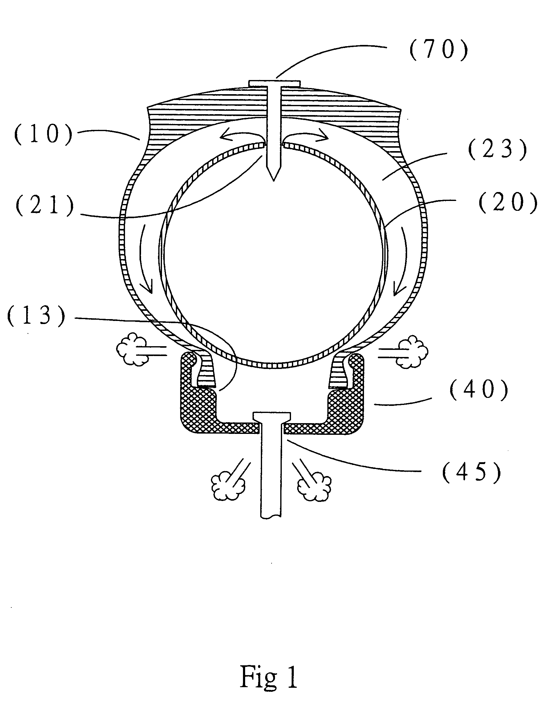
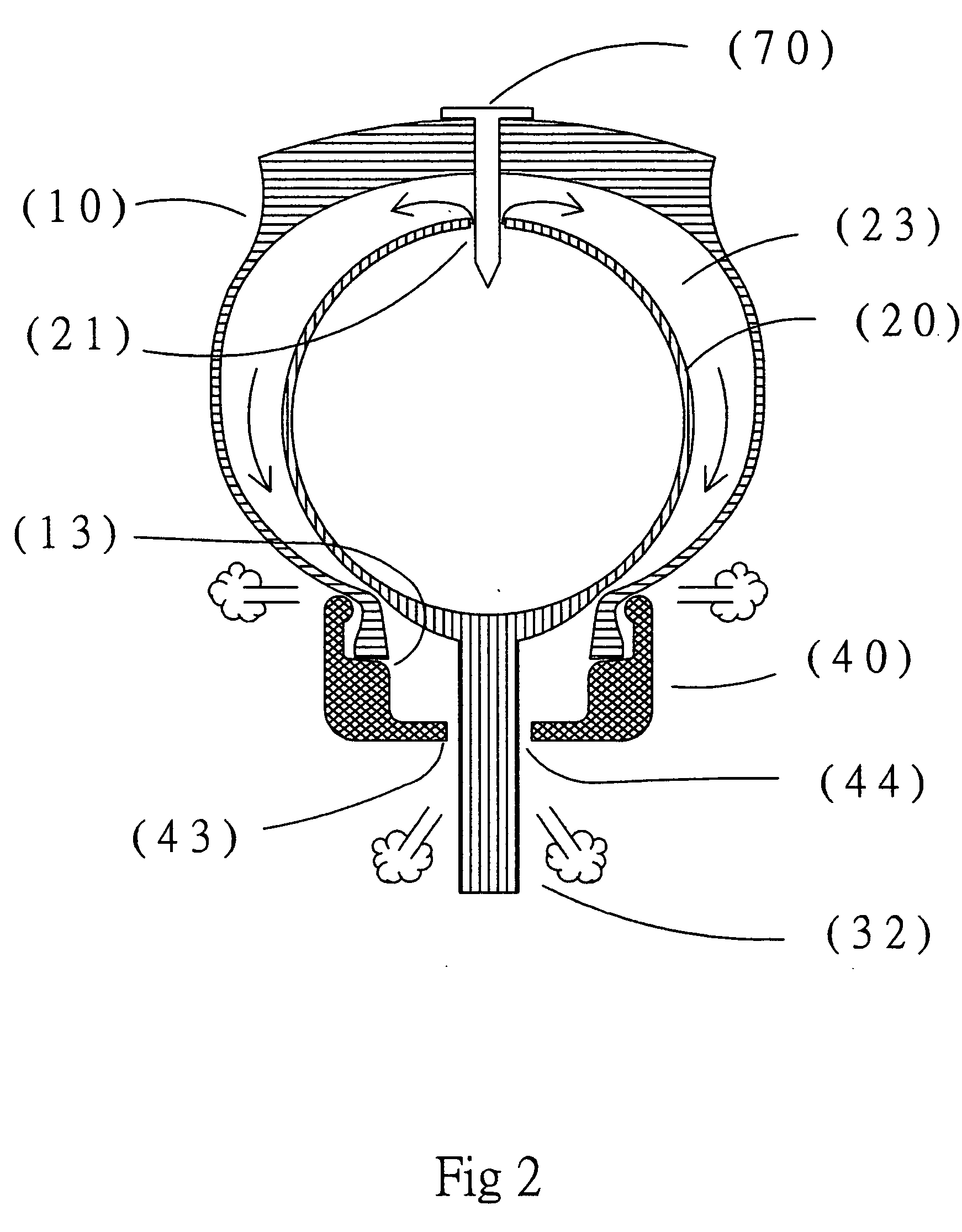
[0027] The function of the safety pneumatic tire is illustrated in FIGS. 3, 4 and 5.

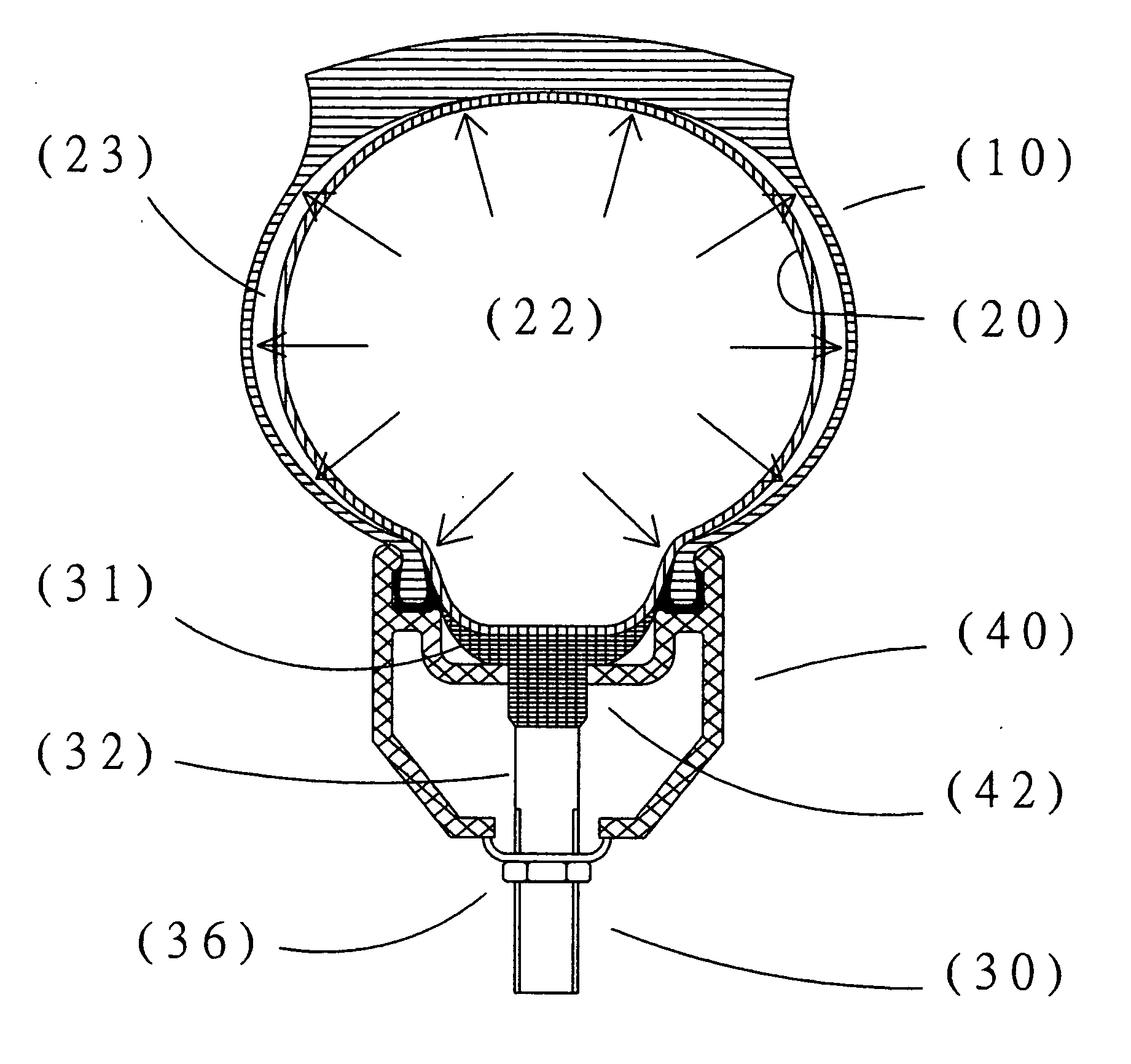
[0028]FIG. 3 displays all the parts that are to be assembled for the safety pneumatic tire. The improved tire (10) has beads (11) that are coated with an elastomeric layer (12). These coated beads (11) are mounted on the bead-seats (41) of the tubeless rim (40). The natural elasticity of the elastomeric material coating (12) naturally ensures a close contact of the tire beads with the rim bead seats (41), which forms an airtight chamber.

[0029] In addition, the elastic rubber-covered valve base (31) of the elastic rubber semi-covered air valve (30) is united (using a process of vulcanization or use of an adhesive) with the inner tube (20) to make the improved inner tube which is incorporated inside the improved tire (10). Where...


PUM


Abstract

The object of this invention is to provide a safety pneumatic tire for the bicyclist. The new safety pneumatic tire comprises an improved outer cover (or tire) and an improved inner tube. The improved inner tube is incorporated inside the improved tire and both are mounted on a tubeless rim (rather than a traditional rim). A) The improved tire consists of an elastomeric material coating that is applied to the beads of the tire to obtain an elastic property. The elastomeric-covered beads and the tubeless rim naturely join closely to form a completely sealed chamber between the tire and the tubeless rim. B) The improved inner tube consists of an elastic rubber part that is added to the outer base of the air valve body or is added to the entire outer body of the air valve to form an air tight seal with the rim valve opening. The joints and the connections between the improved tire, the improved inner tube and the tubeless rim are tightly sealed to form an enclosed chamber so that, if the inner tube is punctured, the compressed air remains inside the enclosed chamber and does not immediately deflate. As a result, any deflation of tire occurs slowly and the bicyclist is protected from falling and is able continue riding. The present invention is also able to avoid the difficulty of air inflation which exists in tubeless tires. In tubeless tires, if inflation of the tire is not rapid enough to create sealing pressure between the tire beads and the tubeless rim bead seat, air will escape during the process of inflation. With the present invention, this difficulty is avoided with the use of the improved inner tube.

Description

BACKGROUND OF THE INVENTION [0001] A) Field of Invention [0002] The present invention relates to a pneumatic tire assembly for the bicycle. This invention especially relates to an improved outer tire and improved inner tube for a pneumatic tire assembly that provides protection against immediate or rapid deflation of the tire when the inner tube is punctured and also allows for easy air inflation of a pneumatic tire by a bicyclist. [0003] B) Description of the Prior Art [0004] The typical bicycle pneumatic tire assembly comprises a traditional tire, a traditional inner tube and a traditional rim. Both the tire and the inner tube are mounted on the corresponding rim. The traditional inner tube comprises a toroidal elastic tube with a traditional air valve. When the inner tube is inflated with the compressed air, the wheel performs the function of providing the bicycle and its load with a pneumatic-type support, and ensures suitable behavior on the road. The deficiency of the traditio...

Claims


Application Information

Patent Timeline
Patent Type & Authority Applications(United States)
IPC IPC(8): B60C5/00
CPCB60C5/04B60C5/16B60C15/024B60C15/06
Inventor KUO, HSU SHWUHSU, MING-CHE
Owner KUO HSU SHWU
Why Eureka
Try Eureka