Closer for containers

a container and close technology, applied in the field of containers, can solve the problems of affecting the operation of the drive system, affecting the operation of the container, and the corresponding cost factor, and achieve the effects of less expensive manufacturing, reduced moving mass, and reduced penetration of soiling and/or germs into the clean room

Active Publication Date: 2013-12-19
KRONES AG
View PDF20 Cites 8 Cited by
  • Summary
  • Abstract
  • Description
  • Claims
  • Application Information

AI Technical Summary

Benefits of technology

[0007]This has the disadvantage that such magnetic couplings involve a corresponding cost factor and that the magnetic couplings must be dimensioned to be correspondingly large for transmitting the required forces, and thus the masses to be moved have disadvantageous effects on the drive system.
[0008]It is one aspect of the present disclosure to provide a closer for containers with a closing head acting in a clean room where the moving masses are reduced and which is less expensive to manufacture. It is another aspect of the present disclosure to provide a closer for containers wherein the penetration of soiling and / or germs into a clean room is reduced.
[0009]These and other aspects of the disclosure are achieved with a closer for containers having features where the closing head is connected to the rotor of an electric motor and an element for clean room separation is formed between the rotor and the stator.
[0010]By the closing head being connected with the rotor of the electric motor, the forces corresponding to the design of the closer can act directly from the magnetic field of the stator upon the rotor and thus be transmitted to the closing head. Thus, the forces do not have to be transmitted via an expensive magnetic coupling of large dimensions, and the moving masses are thus reduced. Simultaneously, the element formed for clean room separation between the stator and the rotor prevents the penetration of soiling and germs into the clean room. Here, the magnetic field acts upon the rotor through the element for clean room separation. In other words, the clean room is hermetically separated from the surrounding area by the element disposed between the stator and the rotor, and thus the separation between the clean room and the surrounding area is disposed within the electric motor. Additionally, a sealing of the clean room is achieved in this way, whereby sealing devices, such as shaft sealing rings or siphon sealings, can be additionally eliminated.
[0011]The containers can in particular comprise plastic bottles, glass bottles, cans and / or tubes. The containers can contain beverages, food, sanitary products, pastes, chemical, biological and / or pharmaceutical products. The closer is particularly suited for closing PET bottles having a collar at which they are supportively held at least during filling and closing. This is the case in particular when microbiologically sensitive products to be filled are filled in cold-aseptic filling lines. The containers can comprise a bottle mouth for screwing on the closing cap. Other closures, such as snap-on closures or crown caps, for example, are also conceivable.
[0012]The containers can be treated in the closer in a clean room. A clean room can be a region with reduced germs or particles of dirt. The clean room can have an overpressure with respect to the surrounding area.

Problems solved by technology

This has the disadvantage that such magnetic couplings involve a corresponding cost factor and that the magnetic couplings must be dimensioned to be correspondingly large for transmitting the required forces, and thus the masses to be moved have disadvantageous effects on the drive system.

Method used


Image

  • Closer for containers
  • Closer for containers
  • Closer for containers

Examples


Embodiment Construction

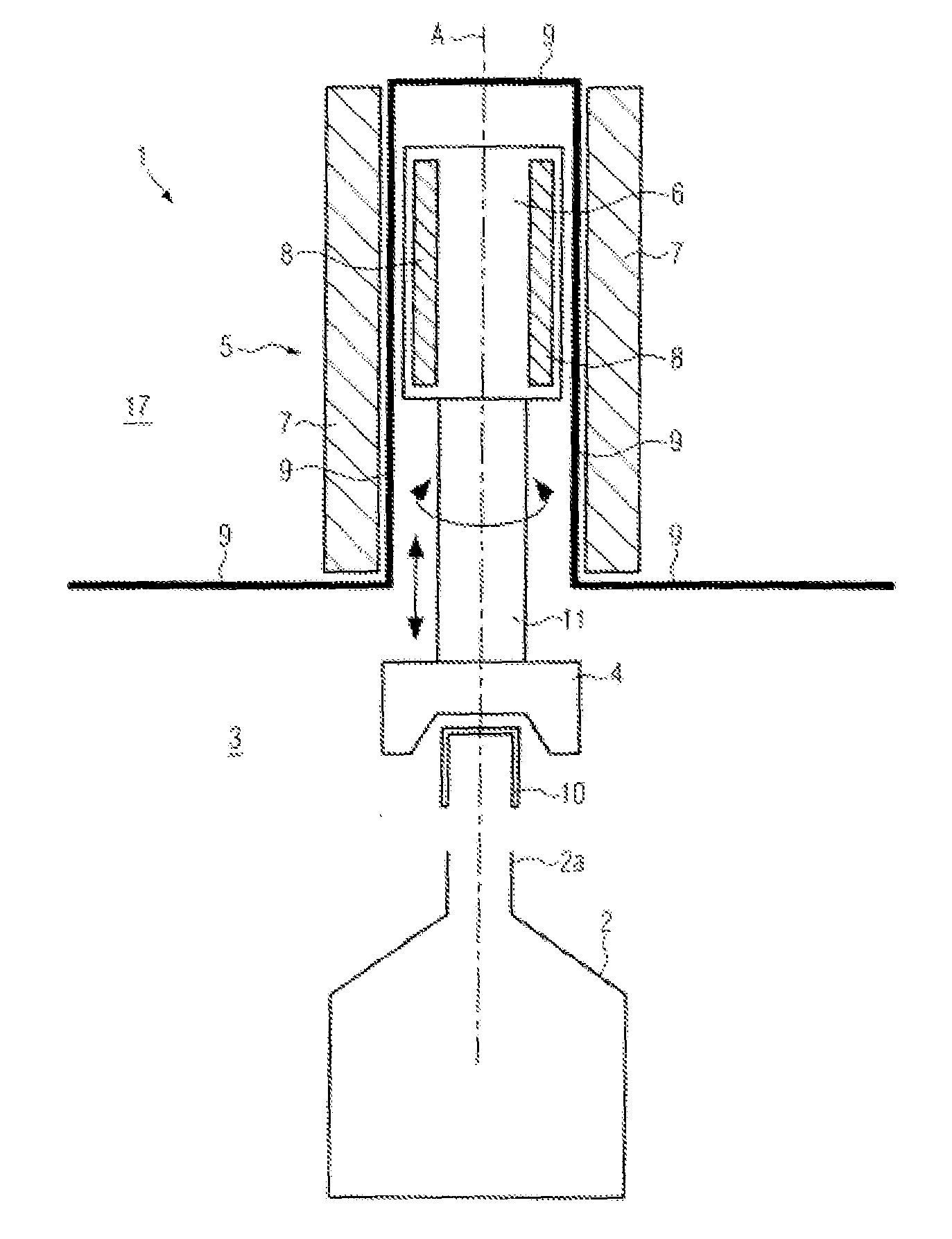
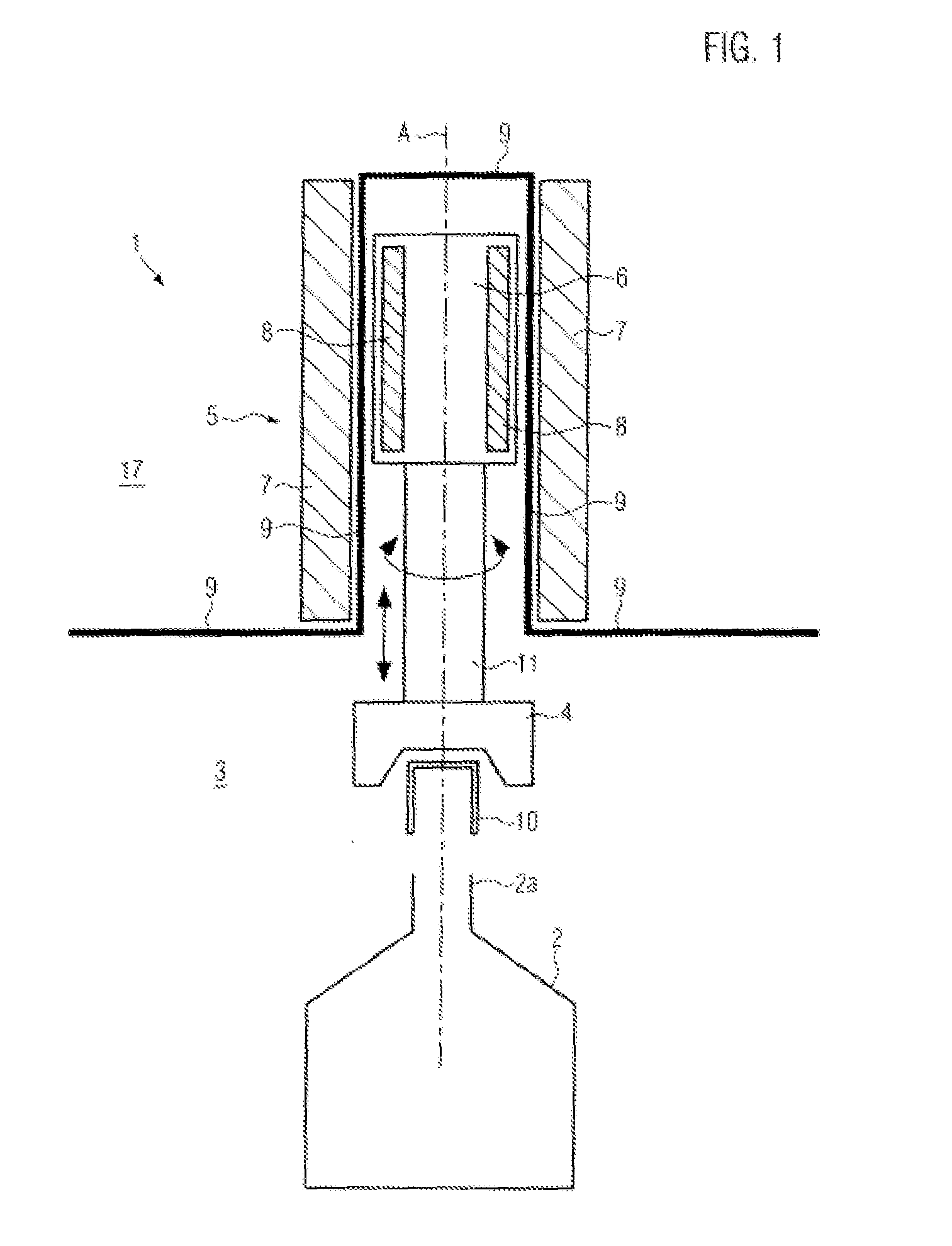
[0027]FIG. 1 shows a representation of a closer 1 in a lateral sectional view. Here, an electric motor 5 moves the closing head 4 via an axle element 11. The closing head 4 first picks up a closing cap 10 and screws the latter onto the container mouth 2a of the container 2 via a lowering rotary motion. The container 2 represented here is a bottle.

[0028]The electric motor 5 is here embodied as a three-phase motor and comprises a stator 7 and a rotor 6 between which an element for clean room separation 9 is formed. This element for clean room separation 9 is here formed as a housing-like shell of non-magnetic plastics and has the shape of a cylinder closed on one side with a rotational symmetry around the axle A. By the element for clean room separation 9, the clean room 3 is thus hermetically separated from the surrounding area 17. Thus, no lubricants from drive units, no particles of dirt and no germs can penetrate from the surrounding area 17 into the clean room 3. Equally, no pres...


PUM


Abstract

A closer for containers, in particular bottles, with a closing head acting in a clean room and with an electric motor comprising at least one rotor and at least one stator, with the closing head connected with the rotor, and an element for clean room separation is formed between the rotor and the stator.

Description

CROSS-REFERENCE TO RELATED APPLICATION[0001]The present application claims the benefit of priority of German Application No. 10 2012 209 905.0, filed Jun. 13, 2012. The entire text of the priority application is incorporated herein by reference in its entirety.FIELD OF THE DISCLOSURE[0002]The disclosure relates to a closer for containers, in particular bottles, with a closing head acting in a clean room and with an electric motor comprising at least one rotor and at least one stator.BACKGROUND[0003]As is well-known, screw caps of containers, for example bottles, can be closed in rotary machines with several circumferentially arranged closers rotating about a common axle, the closing caps each being held in a closing head and rotated as well as lowered corresponding to the thread pitch after having been placed onto the respective bottle mouth. As an alternative, the containers can also be correspondingly lifted while the closing cap is being screwed on. The rotary motion of the closi...

Claims


Application Information

Patent Timeline
Patent Type & Authority Applications(United States)
IPC IPC(8): B65B7/28
CPCB65B7/2871B67B3/2066H02K21/14H02K21/22H02K5/1282H02K16/00B67B2201/08H02K2201/18H02K41/03
Inventor SCHOENFELDER, MARKUSPOESCHL, STEFAN
Owner KRONES AG
Why Eureka
Try Eureka