Laser processing apparatus

Active Publication Date: 2013-12-19
DISCO CORP
View PDF5 Cites 60 Cited by
  • Summary
  • Abstract
  • Description
  • Claims
  • Application Information

AI Technical Summary

Benefits of technology

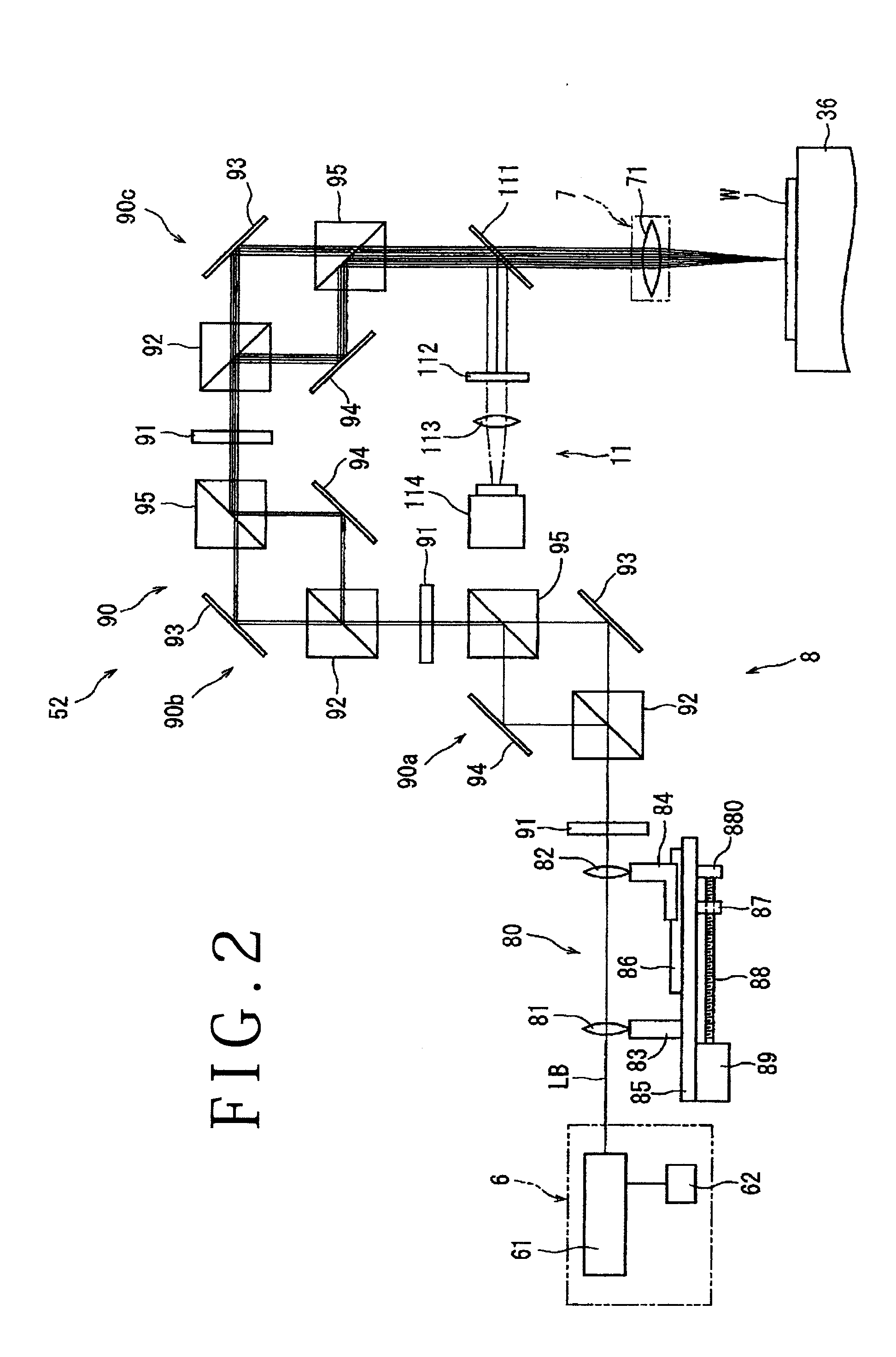
[0014]In the laser processing apparatus according to the present invention, the laser beam branching mechanism provided between the laser beam oscillating means and the focusing means for branching the laser beam oscillated by the laser beam oscillating means into a plurality of laser beams includes the spread angle adjusting means for adjusting the spread angle of the laser beam oscillated by the laser beam oscillating means and the branching unit for branching the laser beam passed through the spread angle adjusting means into the plural laser beams. The branching unit includes the half-wave plate, the first polarization beam splitter for separating the laser beam passed through the half-wave plate into P polarized light and S polarized light, the first mirror for reflecting the P polarized light obtained by the first polarization beam splitter, the second mirror for reflecting the S polarized light obtained

Problems solved by technology

In the technique described in Japanese Patent Laid-Open No. 2011-156551, however, it is difficult to adjust the spacing between the plural focused spots (focal points)

Method used


Image

  • Laser processing apparatus
  • Laser processing apparatus
  • Laser processing apparatus

Examples


Example

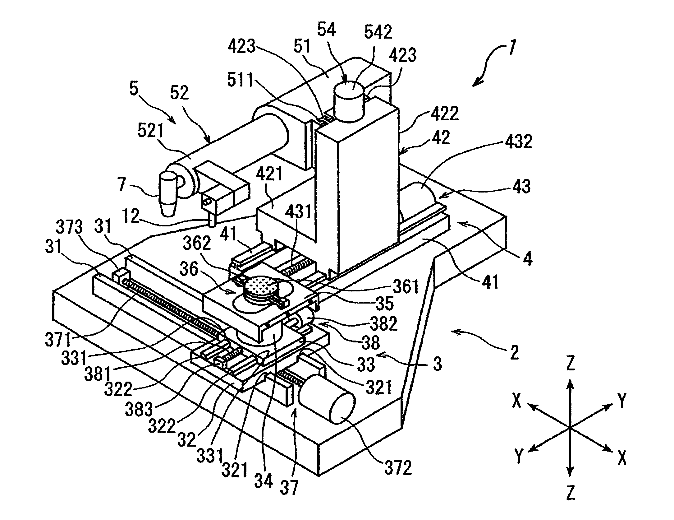
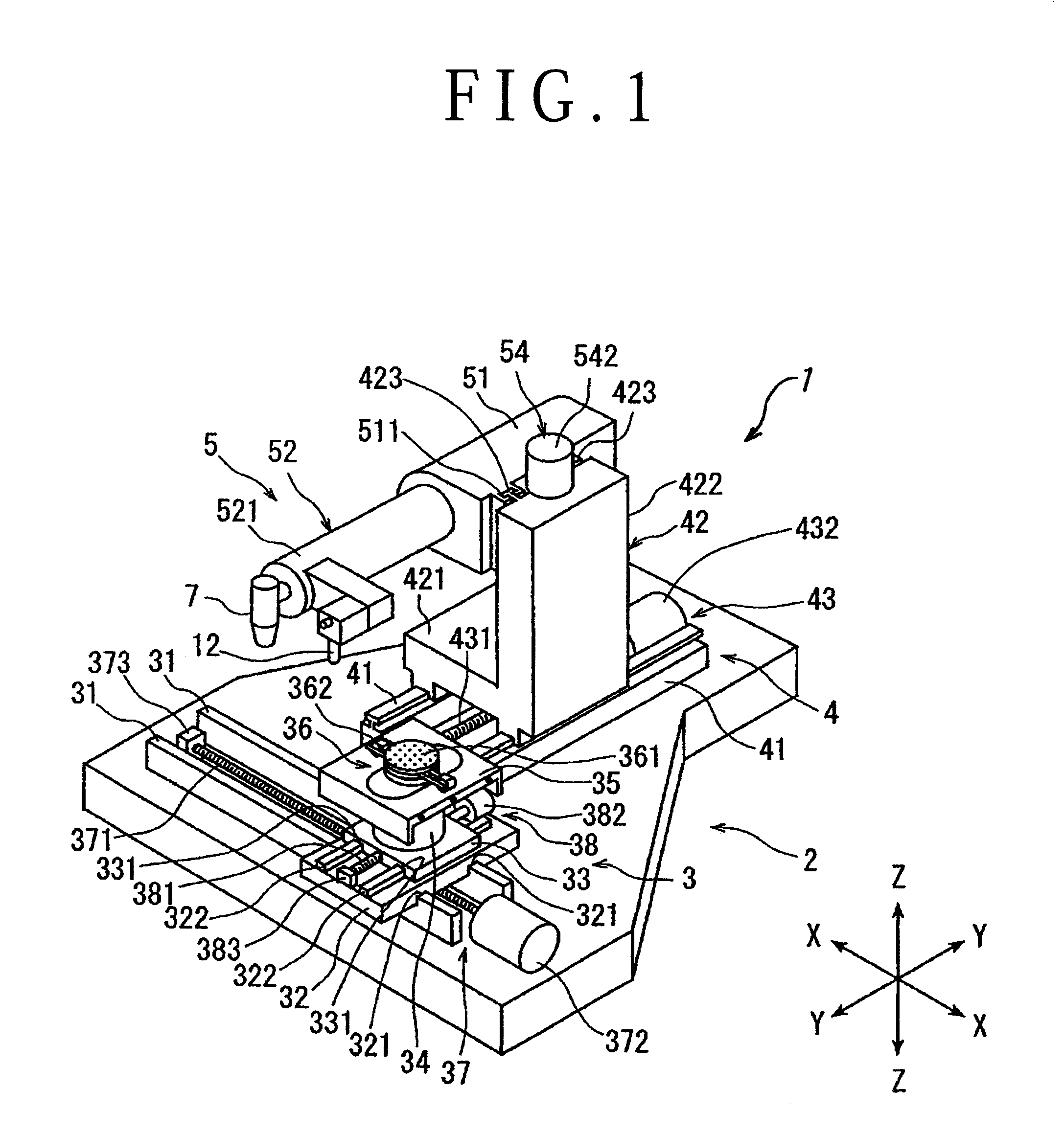
[0027]A preferred embodiment of the laser processing apparatus according to the present invention will now be described in detail with reference to the attached drawings. FIG. 1 is a perspective view of a laser processing apparatus 1 according to a preferred embodiment of the present invention. The laser processing apparatus 1 shown in FIG. 1 includes a stationary base 2, a chuck table mechanism 3 for holding a workpiece, the chuck table mechanism 3 being provided on the stationary base 2 so as to be movable in a feeding direction (X direction) shown by an arrow X, a laser beam applying unit supporting mechanism 4 provided on the stationary base 2 so as to be movable in an indexing direction (Y direction) shown by an arrow Y perpendicular to the X direction, and a laser beam applying unit 5 provided on the laser beam applying unit supporting mechanism 4 so as to be movable in a focal position adjusting direction (Z direction) shown by an arrow Z.

[0028]The chuck table mechanism 3 inc...


PUM

PropertyMeasurementUnit
Angleaaaaaaaaaa

Abstract

A laser processing apparatus including a laser beam branching mechanism provided between a laser oscillator and a focusing unit. The laser beam branching mechanism includes a spread angle adjusting unit for adjusting the spread angle of a laser beam and a branching unit for branching the laser beam into a plurality of laser beams. The branching unit includes a half-wave plate, a first polarization beam splitter for separating the laser beam into P polarized light and S polarized light, a first mirror for reflecting the P polarized light, a second mirror for reflecting the S polarized light, and a second polarization beam splitter for leading the P polarized light reflected by the first mirror and the S polarized light reflected by the second mirror to different optical paths extending in the same direction.

Description

BACKGROUND OF THE INVENTION[0001]1. Field of the Invention[0002]The present invention relates to a laser processing apparatus suitable for formation of a laser processed groove by applying a laser beam along a street formed on the front side of a workpiece such as a semiconductor wafer.[0003]2. Description of the Related Art[0004]In a semiconductor device fabrication process, a multilayer film composed of an insulating film and a functional film is formed on the front side of a semiconductor substrate such as a silicon substrate, and a plurality of devices such as ICs and LSIs are formed like a matrix from this multilayer film, thus obtaining a semiconductor wafer having the plural devices. The plural devices are partitioned by a plurality of division lines called streets formed on the front side of the semiconductor wafer. The semiconductor wafer is divided along these streets to obtain the individual devices.[0005]Division of the semiconductor wafer along the streets is usually pe...

Claims


Application Information

Patent Timeline
IPC IPC(8): B23K26/02
CPCB23K26/02B23K26/042B23K26/364B23K26/067B23K26/0676B23K26/0853B23K26/0869B23K26/06B23K26/0643B23K26/38B23K2103/56
Inventor NOMARU, KEIJI
Owner DISCO CORP
Why Eureka
Try Eureka