Imaging lens assembly

a technology of lens assembly and optical imaging signal, which is applied in the field of imaging lens assembly, can solve the problems of serious distortion of the imaging of optical imaging signal compared with the imaging of original optical imaging signal, large chromatic aberration, and large astigmatism, and achieve the effect of improving the imaging quality of the camera device and improving the imaging quality

Inactive Publication Date: 2013-12-19
GLORY SCI
View PDF1 Cites 2 Cited by
  • Summary
  • Abstract
  • Description
  • Claims
  • Application Information

AI Technical Summary

Benefits of technology

[0008]As described above, the imaging lens assembly effectively corrects and compensates the aberration, the field curvature, the astigmatism and the distortion of the imaging lens assembly by means of the first lens having positive refractive power and the convex object-side surface, the second lens having negative refractive power and the concave image-side surface, at least one surface of the image-side surface and an object-side surface of the second lens being aspheric, the third lens having positive refractive power, the concave object-side surface and the convex image-side surface of which at least one surface is aspheric, the fourth lens having positive refractive power, the concave object-side surface and a convex image-side surface of which at least one surface is aspheric, the fifth lens having negative refractive power, the concave object-side surface and the concave image-side surface which are aspheric. Thereby, the imaging lens assembly has the miniaturized and proper configuration for being used in the miniaturized camera device and further improving an imaging quality of the camera device to get the better imaging quality.

Problems solved by technology

However, if the imaging lens assembly has the improper configuration, when the optical imaging signals are through the lenses, various parameters of each lens, such as the radius of curvature and the refractive index of the lens will affect the imaging of the optical imaging signals that results in the larger chromatic aberration, the larger astigmatism and the serious distortion of the imaging of the optical imaging signals compared with the imaging of the original optical imaging signals.
Thereby, the camera device has the poor imaging quality.

Method used


Image

  • Imaging lens assembly
  • Imaging lens assembly
  • Imaging lens assembly

Examples


first embodiment

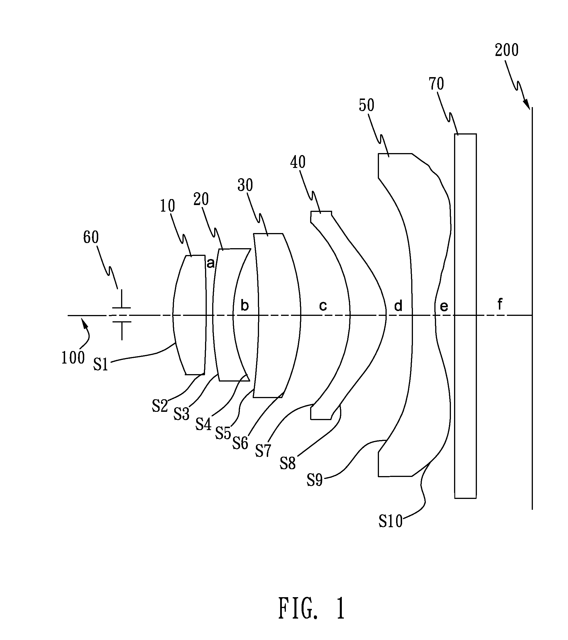
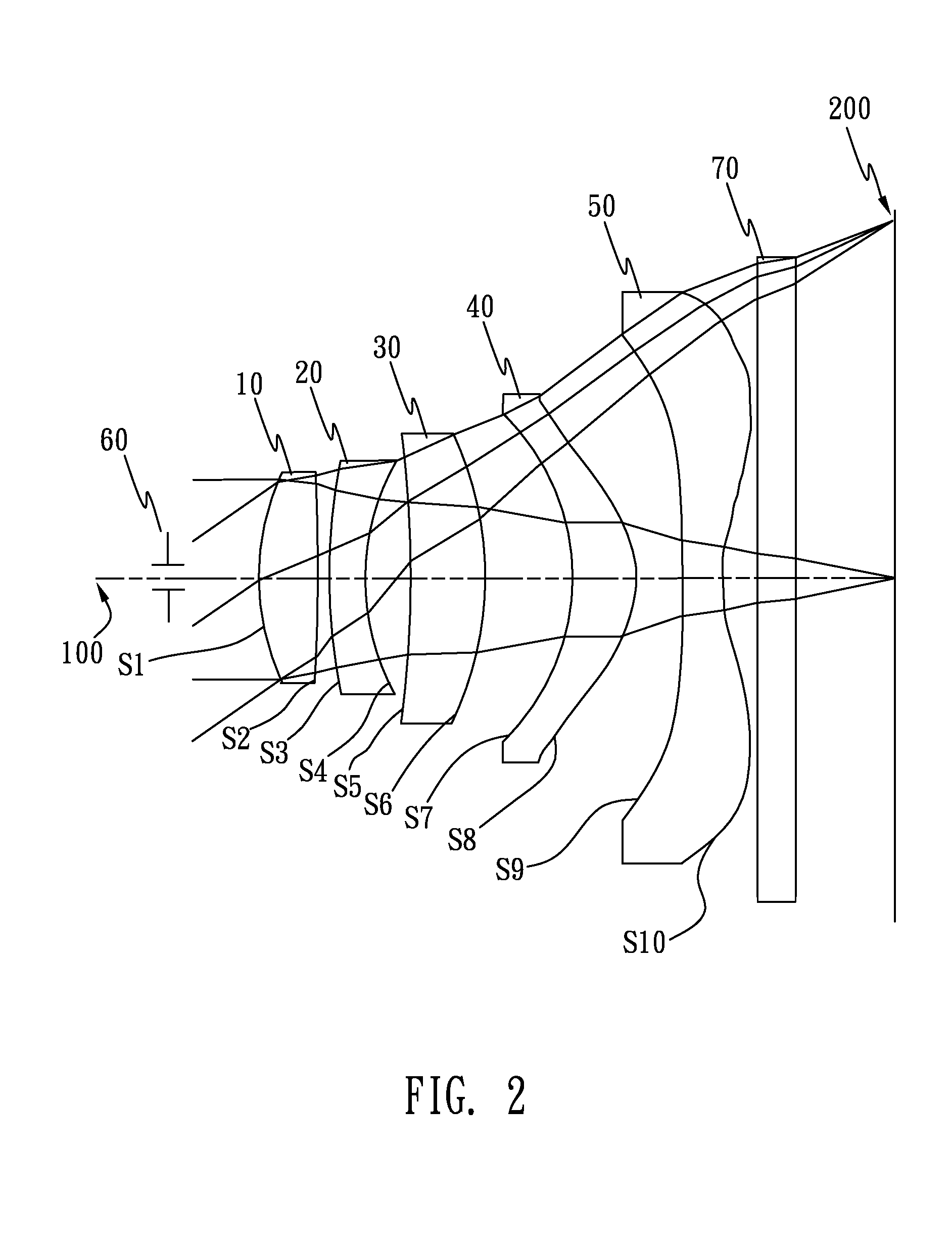
[0031]In the present imaging lens assembly, the imaging lens assembly meets the relations: f1 / f=0.7256, f3 / f=1.9648, f4 / f=0.6781, R1 / f=0.4818, R4 / f=0.3564, R6 / f10 is f1, the focal length of the third lens 30 is f3, the focal length of the fourth lens 40 is f4, R1 is the radius of curvature of the object-side surface S1 of the first lens 10, R4 is the radius of curvature of the image-side surface S4 of the second lens 20, R6 is the radius of the curvature of the image-side surface S6 of the third lens 30, and R8 is the radius of the curvature of the image-side surface S8 of the fourth lens 40.

[0032]The equation of the aspheric surfaces of the first lens 10, the second lens 20, the third lens 30, the fourth lens 40 and the fifth lens 50 is expressed as follows:

Z=ch21+(1-(K+1)c2h2)+Ah4+Bh6+CH8+Dh10+Eh12+Fh14+Gh16+Hh18+Jh20

[0033]Wherein c is the lens curvature, h is a vertical distance between the surface of each lens and an optical axis of the imaging lens assembly, k is a conic consta...

second embodiment

[0036]In the present imaging lens assembly, the imaging lens assembly meets the relation: f1 / f=0.7082, f3 / f=2.2001, f4 / f=0.6606, R1 / f=0.4457, R4 / f=0.3705, R6 / f10 is f1, the focal length of the third lens 30 is f3, the focal length of the fourth lens 40 is f4, R1 is the radius of curvature of the object-side surface S1 of the first lens 10, R4 is the radius of curvature of the image-side surface S4 of the second lens 20, R6 is the radius of the curvature of the image-side surface S6 of the third lens 30, and R8 is the radius of the curvature of the image-side surface S8 of the fourth lens 40.

[0037]The equation of the aspheric surfaces of the first lens 10, the second lens 20, the third lens 30, the fourth lens 40 and the fifth lens 50 is expressed as follows:

Z=ch21+(1-(K+1)c2h2)+Ah4+Bh6+CH8+Dh10+Eh12+Fh14+Gh16+Hh18+Jh20

[0038]Wherein c is the lens curvature, h is the vertical distance between the surface of each lens and an optical axis of the imaging lens assembly, k is the conic con...

third embodiment

[0041]In the present imaging lens assembly, the imaging lens assembly meets the relation: f1 / f=0.6817, f3 / f=2.2001, f4 / f=0.6181, R1 / f=0.4111, R4 / f=0.3818, R6 / f10 is f1, the focal length of the third lens 30 is f3, the focal length of the fourth lens 40 is f4, R1 is the radius of curvature of the object-side surface S1 of the first lens 10, R4 is the radius of curvature of the image-side surface S4 of the second lens 20, R6 is the radius of the curvature of the image-side surface S6 of the third lens 30, and R8 is the radius of the curvature of the image-side surface S8 of the fourth lens 40.

[0042]The equation of the aspheric surfaces of the first lens 10, the second lens 20, the third lens 30, the fourth lens 40 and the fifth lens 50 is expressed as follows:

Z=ch21+(1-(K+1)c2h2)+Ah4+Bh6+CH8+Dh10+Eh12+Fh14+Gh16+Hh18+Jh20

[0043]Wherein c is the lens curvature, h is the vertical distance between the surface of each lens and an optical axis of the imaging lens assembly, k is the conic con...


PUM


Abstract

An imaging lens assembly includes a first lens, a second lens, a third lens, a fourth lens and a fifth lens arranged in sequence from an object side to an image side. The first lens has positive refractive power and a convex object-side surface. The second lens has negative refractive power and a concave image-side surface. At least one surface of the image-side surface and an object-side surface of the second lens is aspheric. The third lens has positive refractive power, a concave object-side surface and a convex image-side surface of which at least one surface is aspheric. The fourth lens has positive refractive power, a concave object-side surface and a convex image-side surface of which at least one surface is aspheric. The fifth lens has negative refractive power, a concave object-side surface and a concave image-side surface which are aspheric.

Description

BACKGROUND OF THE INVENTION[0001]1. Field of the Invention[0002]The present invention generally relates to an imaging lens assembly, and more particularly to a compact imaging lens assembly capable of being used in a miniaturized camera device.[0003]2. The Related Art[0004]Nowadays, electronic technology has developed faster and faster, more and more camera devices are used in people's daily lives. It's a trend for the people to pursue a miniaturization of the camera device so as to be used in a miniaturized camera device, and in the meantime, an image of an object shot by the camera device has been requested a higher quality, namely, the image of the object shot by the camera device is clear. An imaging quality of the camera device is mainly depended on a configuration of an imaging lens assembly used in the camera device. Currently, the imaging lens assembly mostly includes multiple lenses. Optical imaging signals are focused on an image sensor of the camera device through the ima...

Claims


Application Information

Patent Timeline
Patent Type & Authority Applications(United States)
IPC IPC(8): G02B13/00
CPCG02B13/18G02B13/0045
Inventor CHANG, SHIH-YUANCHUNG, FENG-CHAO
Owner GLORY SCI
Why Eureka
Try Eureka