

Aircraft
a technology for aircraft and propellers, applied in the field of aircraft, can solve the problems of reducing the fuel efficiency of aircraft, affecting the operation life of fan blades, increasing noise and vibration, etc., and achieve the effect of improving aerodynamic efficiency
- Summary
- Abstract
- Description
- Claims
- Application Information
AI Technical Summary
Benefits of technology
Problems solved by technology
Method used
Image

Examples
Embodiment Construction
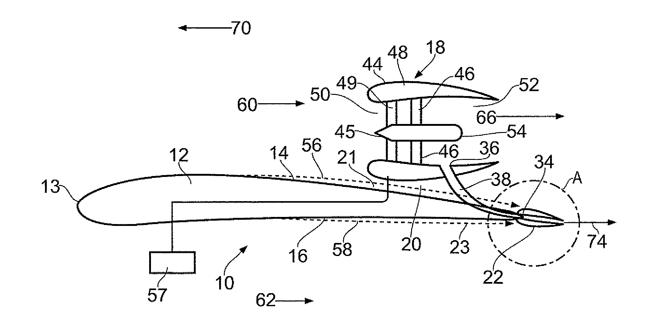
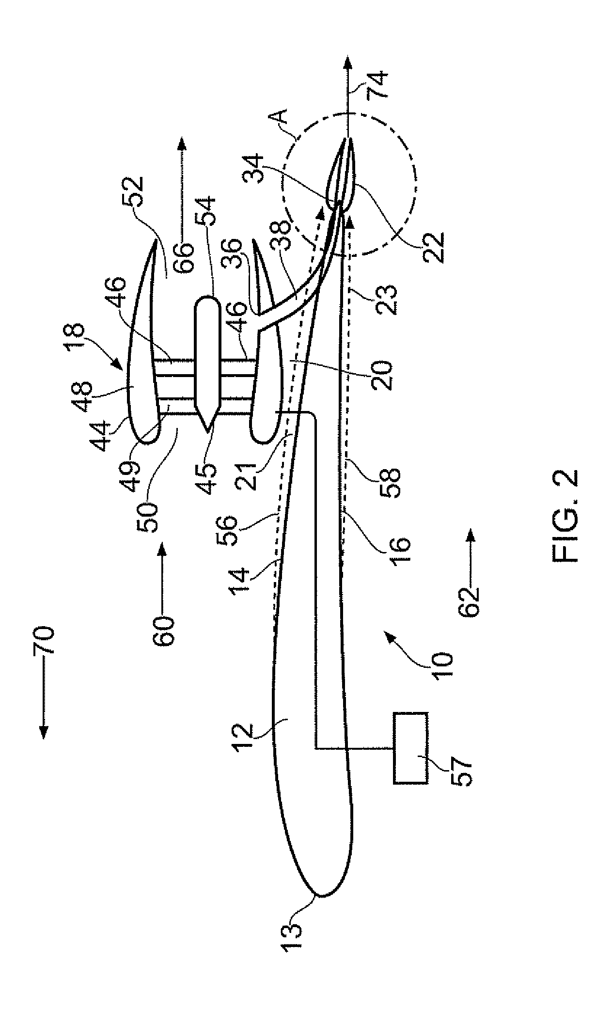
[0030]FIG. 2 shows a sectional view of an aerofoil of an aircraft 10 in the form a wing 12 and FIG. 3 shows a view of the upper surface of the wing 12 from the front of the aircraft 10. The aircraft 10 could be a conventional tube and wing design (similar to that shown in FIG. 7 for example), in which a wing 12 spans horizontally and generally perpendicularly to a generally tubular fuselage 13. Alternatively, the aircraft could comprise a Blended Wing Body aircraft, in which the wing is attached to an airfoil section fuselage, such that both the wing and the fuselage contribute to lift.
[0031]The wing 12 includes a generally outwardly arcuate suction surface 14 on an upper side, and a pressure surface 16 on a lower side, a leading edge 13 and a trailing edge 34. Together, the suction and pressure surfaces 14, 16 and leading and trailing edges 13, 34, define an aerofoil section, which is arranged to generate lift when the wing is moved in a direction 70 as is well known in the art. Th...
PUM
 Abstract
Description
Claims
Application Information