Control apparatus for an internal combustion engine

a control apparatus and internal combustion engine technology, applied in the direction of engine controllers, electric control, machines/engines, etc., can solve the problems of difficult to estimate the concentration of evaporated fuel with high accuracy, the air-fuel ratio of the engine may greatly vary, and the emission may worsen, so as to maintain the emission at a preferable level, and the effect of “oxygen storage capacity of the catalys

Inactive Publication Date: 2013-12-26
TOYOTA JIDOSHA KK
View PDF5 Cites 9 Cited by
  • Summary
  • Abstract
  • Description
  • Claims
  • Application Information

AI Technical Summary

Benefits of technology

[0006]In the meantime, the applicant is developing an air-fuel ratio control apparatus which can maintain emissions at a preferable level especially when the “oxygen storage capacity of the catalyst is low (e.g., when a maximum oxygen storage amount is small such as when the catalyst has deteriorated, or when the oxygen storage capacity itself is small)”. For example, one of such air-fuel ratio control apparatuses being developed determines a state (oxygen storage state) of the catalyst based on the output value of the downstream air-fuel ratio sensor without delay, and controls the air-fuel ratio of the engine in such a manner that an air-fuel ratio of the catalyst inflow gas coincide with an air-fuel ratio other than the stoichiometric air-fuel ratio based on a result of the determination.
[0010]The present invention is made to cope with the above described problem. That is, one of the objects of the present invention is to provide a control apparatus for an internal combustion engine, which can reduce a degree of worsening of the emission when the evaporated fuel pure is carried out.
[0024]Further, the evaporated fuel purge amount control section of the present invention is configured so as to increase the purge amount as a magnitude of a difference between the target lean air-fuel ratio and the target rich air-fuel ratio becomes larger.
[0029]Accordingly, in the present invention apparatus, a time period in which the oxygen storage amount is maintained at the “maximum oxygen storage amount Cmax” or “0” (that is, a time duration in which the emission worsens) becomes shorter, even if a large amount of the evaporated fuel is purged, and thus, the air-fuel ratio of the catalyst inflow gas greatly fluctuates. Consequently, the present invention apparatus can carry out the purge of the evaporated fuel while maintaining the possibility that the emission worsens at a low level.
[0035]According to the configuration described above, the purge amount can be increased as an amount of the evaporated fuel adsorbed in the canister (estimated adsorbed amount of the evaporated fuel) comes closer to the canister saturated evaporated fuel amount, and thus, it is possible to provide the canister with a capacity to adsorb a “certain (fair) amount of the evaporated fuel.” Thus, even when a large amount of the evaporated fuel suddenly / rapidly generates in the fuel tank, there is a high possibility of causing such an evaporated fuel to be adsorbed into the canister. Consequently, a possibility that the evaporated fuel is discharged into the air can be reduced.
[0052]Accordingly, the purge amount can be increased, as an amount of the evaporated fuel which is adsorbed in the canister (estimated adsorbed amount of the evaporated fuel) comes closer to the canister saturated evaporated fuel amount. Thus, it is possible to provide the canister with a capacity to adsorb a “certain (fair) amount of the evaporated fuel.” Therefore, even when a large amount of the evaporated fuel suddenly / rapidly generates in the fuel tank, there is a high possibility of causing such an evaporated fuel to be adsorbed into the canister. Consequently, a possibility that the evaporated fuel is discharged into the air can be reduced. In addition, as the purge amount becomes larger, the magnitude of the difference between the target lean air-fuel ratio and the target rich air-fuel ratio becomes larger, and therefore, a change speed of the air-fuel ratio of the catalyst inflow gas becomes larger. Consequently, a “possibility that the emission worsens due to the purge” can be reduced.

Problems solved by technology

Typically, the control apparatus estimates, based on the output value of the upstream air-fuel ratio sensor, a concentration of the evaporated fuel which is purged, and adjusts a fuel injection amount in accordance with the estimated concentration of the evaporated fuel in order to avoid a “large change in the air-fuel ratio of the engine due to the evaporated fuel purge.” It is not easy, however, to estimate the concentration of the evaporated fuel with high accuracy.
Therefore, if the purge is started when the estimation accuracy of the concentration of the evaporated fuel is not high, the air-fuel ratio of the engine may greatly vary, whereby the emission may worsen.

Method used


Image

  • Control apparatus for an internal combustion engine
  • Control apparatus for an internal combustion engine
  • Control apparatus for an internal combustion engine

Examples


first embodiment

(Configuration)

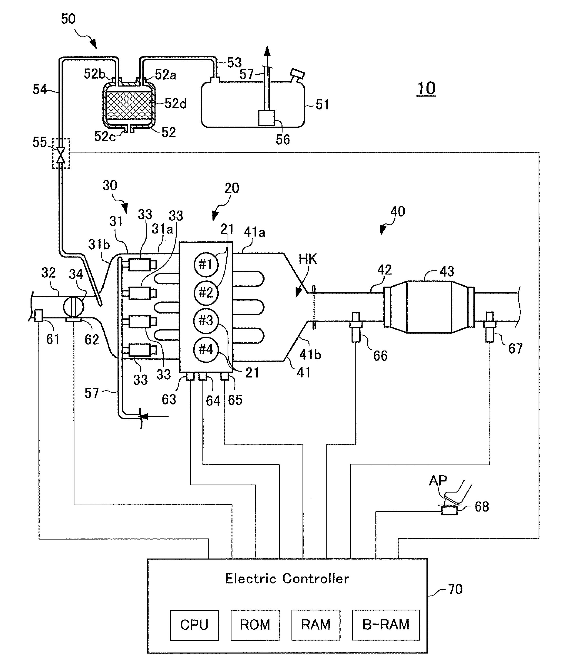
[0067]FIG. 1 schematically shows a configuration of a system configured such that a control apparatus (hereinafter, referred to as a “first control apparatus”) according to a first embodiment is applied to a spark-ignition multi-cylinder (straight 4-cylinder) four-cycle internal combustion engine 10.

[0068]The internal combustion engine 10 includes a main body section 20, an intake system 30, an exhaust system 40, and an evaporated fuel supplying system 50.

[0069]The main body section 20 includes a cylinder block section and a cylinder head section. The main body section 20 has a plurality of cylinders (combustion chambers) 21. Each of the cylinders communicates with unillustrated “intake ports and exhaust ports.” The communicating portions between the intake ports and the combustion chambers are opened and closed by unillustrated intake valves. The communicating portions between the exhaust ports and the combustion chambers are opened and closed by unillustrated exhaus...

second embodiment

[0220]Next, there will be described a control apparatus for an internal combustion engine according to a second embodiment of the present invention (hereinafter, simply referred to as a “second control apparatus”).

[0221]The canister 52 retains the adsorbent material, and therefore, there is an upper limit on an amount of the evaporated fuel which the canister can adsorb. This upper limit is also referred to as a canister saturated evaporated fuel amount. Since the evaporated fuel gas concentration becomes higher as an “amount of the evaporated fuel adsorbed in the canister 52” comes closer to the canister saturated evaporated fuel amount, the evaporated fuel gas concentration learning value FGPG becomes smaller. In view of the above, the second control apparatus obtains, as a value indicative of an “amount of the evaporated fuel adsorbed in the canister 52”, that is, an estimated adsorbed amount of the evaporated fuel, a value (1-FGPG) obtained by subtracting the evaporated fuel gas...


PUM


Abstract

An embodiment (control apparatus) for an internal combustion engine according to the present invention determines, based on an output value of the downstream air-fuel ratio sensor disposed downstream of a three-way catalyst, determines which air-fuel ratio request, a rich request or a lean request, is occurring. The control apparatus sets a target upstream air-fuel ratio to a target rich air-fuel ratio when the rich request is occurring, and sets the target upstream air-fuel ratio to a target lean air-fuel ratio when the lean request is occurring. Each of the target rich air-fuel ratio and the target lean air-fuel ratio is varied depending on an intake air amount. Further, the control apparatus increases a purge amount of an evaporated fuel as a magnitude (air-fuel ratio change amount ΔAF, |afLean−afRich|) of a difference between the target rich air-fuel ratio and the target lean air-fuel ratio becomes larger.

Description

TECHNICAL FIELD[0001]The present invention relates to a control apparatus for an internal combustion engine, having a three-way catalyst disposed in an exhaust passage, an evaporated fuel purge section configured to introduce evaporated fuel generated in a fuel tank into an intake passage, and a fuel injection valve configured to supply fuel.BACKGROUND ART[0002]Conventionally, a three-way catalyst is disposed / provided in an exhaust passage of an internal combustion engine to purify an exhaust gas discharged from the engine. As is well known, the three-way catalyst has an oxygen storage function. That is, the three-way catalyst stores oxygen and reduces NOx when a gas flowing into the there-way catalyst (catalyst inflow gas) contains excessive oxygen. When the catalyst inflow gas contains excessive unburnt substance, the three-way catalyst releases the stored oxygen to purify the unburnt substance. Hereinafter, the three-way catalyst is also referred to as a “catalyst.”[0003]A conven...

Claims


Application Information

Patent Timeline
Patent Type & Authority Applications(United States)
IPC IPC(8): F01N3/08
CPCF01N3/08F02D41/0032F02D41/1441F02D41/0295F02D41/0045
Inventor SUZUKI, KENJIOKAZAKI, SHUNTARO
Owner TOYOTA JIDOSHA KK
Why Eureka
Try Eureka