Wedge bonder and a method of cleaning a wedge bonder

Active Publication Date: 2013-12-26
ASMPT SINGAPORE PTE LTD
View PDF2 Cites 9 Cited by
  • Summary
  • Abstract
  • Description
  • Claims
  • Application Information

AI Technical Summary

Benefits of technology

This patent describes a device called a wedge boder, which is used to bond wires to surfaces to create electrical connections. The device includes a wedge, a cleaning device, and a positioning device. The positioning device moves the wedge to the cleaning device for cleaning. The patent also includes a method for cleaning the wedge after it has been used. The technical effect of this invention is to provide a more efficient and effective way for bonding wires to surfaces, with a higher level of cleanliness and durability.

Problems solved by technology

These tasks are not just time-consuming but also require skilled technicians to undertake.

Method used


Image

  • Wedge bonder and a method of cleaning a wedge bonder
  • Wedge bonder and a method of cleaning a wedge bonder
  • Wedge bonder and a method of cleaning a wedge bonder

Examples


Embodiment Construction

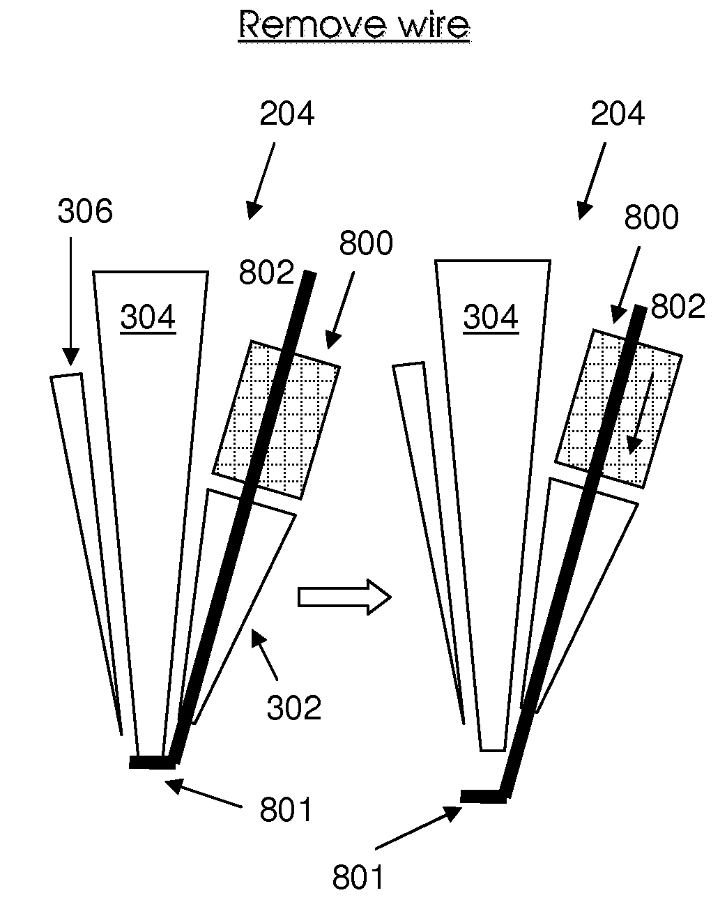
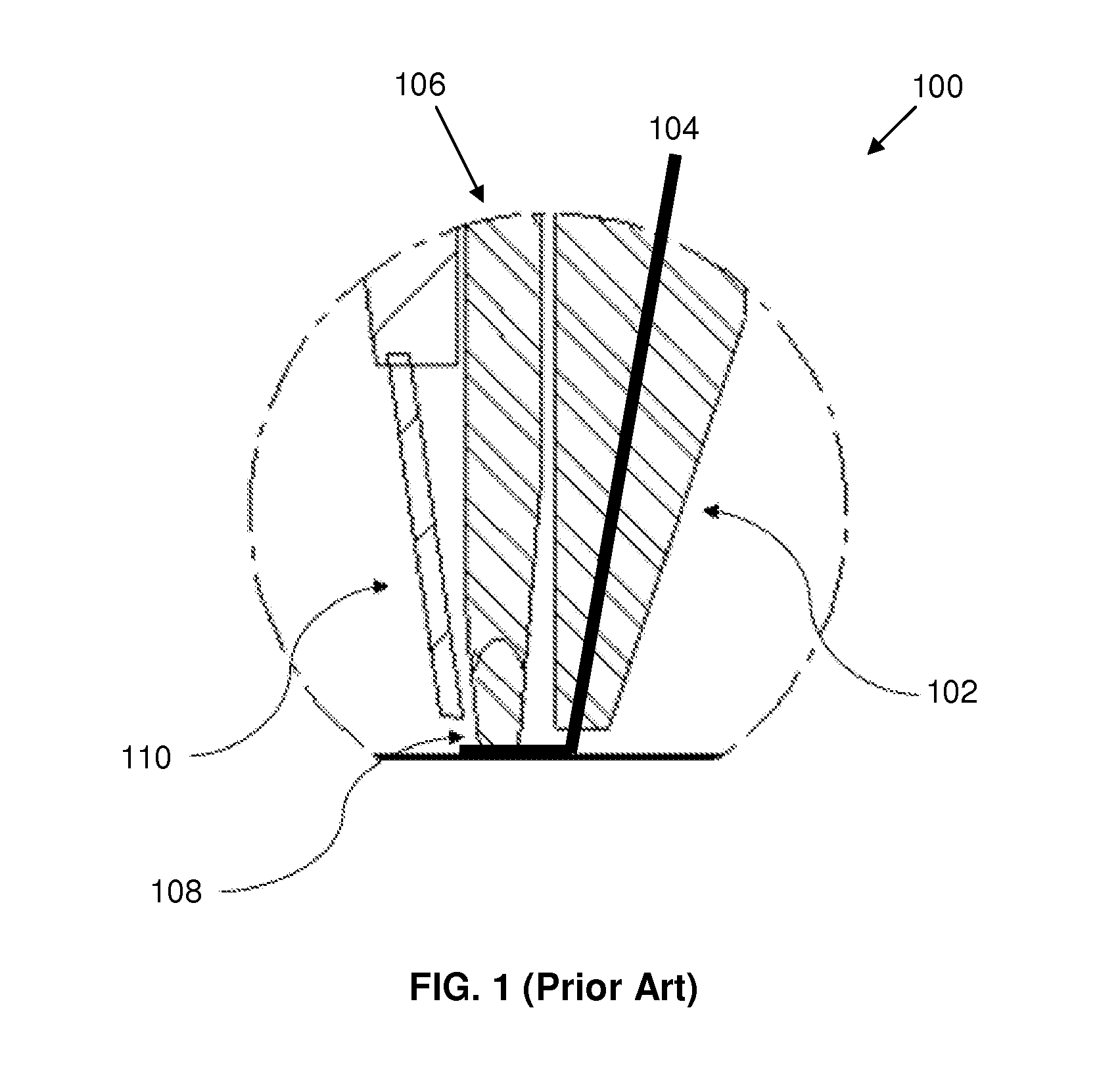
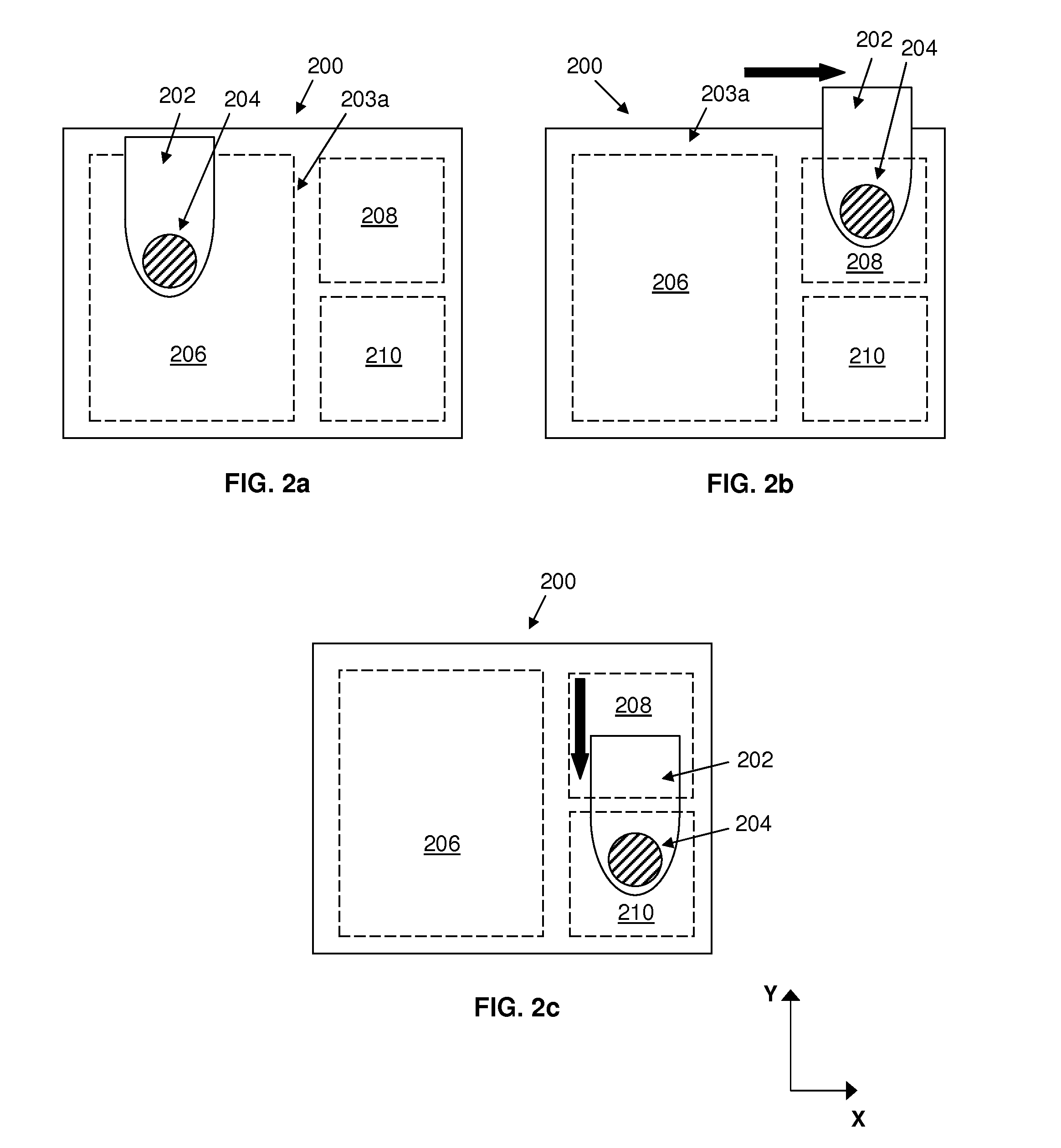
[0021]FIG. 2a-2c are plan views of a wedge bonder 200, showing a positioning device (illustrated by an XY-table 202) and a bond tip 204 mounted to the XY-table 202. Similar to the bond tip shown in FIG. 1, the bond tip 204 may comprise: i) a wire guide for guiding a wire from a wire spool through the bond tip 204; ii) a wedge having a bonding portion for pressing a portion of the wire against a bonding pad of semiconductor die and a bonding pad of a substrate during bonding; and iii) a wire cutter for cutting the wire to detach the wire from the wire spool after an electrical interconnection is formed between the semiconductor die and the substrate.

[0022]In addition, the wedge bonder 200 comprises: i) a bonding zone 206 for supporting a substrate (e.g. a lead frame) when performing bonding operations; ii) an imaging zone 208 for inspecting the wedge; and iii) a cleaning zone 210 for cleaning the wedge.

[0023]Specifically, actuation of the XY-table 202 is controlled by a motion contro...


PUM


Abstract

Disclosed is a wedge bonder, comprising a wedge for bonding a wire to surfaces to form an electrical interconnection therebetween, a cleaning device for cleaning the wedge, and a positioning device to which the wedge is mounted. In particular, the positioning device is operative to move the wedge to the cleaning device for cleaning. A method of cleaning a wedge of a wedge bonder is also disclosed.

Description

FIELD OF THE INVENTION [0001]The present invention relates to a wedge bonder having a wedge for bonding a wire to surfaces to form an electrical interconnection therebetween. In particular, the wedge bonder further comprises a cleaning device for cleaning the wedge. The invention also relates to a method of cleaning a wedge of a wedge bonder.BACKGROUND OF THE INVENTION [0002]A wedge bonder utilizes ultrasonic energy to bond a wire to a semiconductor die and to a substrate to which is mounted, so as to form an electrical interconnection between the semiconductor die and the substrate. Specifically, as the wedge presses the wire against a die pad of the semiconductor die or against the substrate, an ultrasonic transducer generates ultrasonic oscillations that are transmitted through a wedge of a bond tip of the wedge bonder and onward to the wire positioned beneath the wedge.[0003]FIG. 1 shows a bond tip 100 of a conventional wedge bonder, comprising: i) a wire guide 102 for guiding a...

Claims


Application Information

Patent Timeline
IPC IPC(8): B23K3/00B08B7/04
CPCH01L24/78H01L2224/78313H01L2224/4847H01L2924/00014H01L24/45H01L24/85H01L2224/45124H01L2224/7801H01L2224/78901H01L2224/85122H01L2224/78753H01L2224/85205H01L2224/7855H01L24/48H01L2224/45014H01L2924/00H01L2924/206
Inventor CHENG, CHI WAHMUI, MAN KIT
Owner ASMPT SINGAPORE PTE LTD
Why Eureka
Try Eureka