Touch determination with signal compensation

Inactive Publication Date: 2013-12-26
FLATFROG LAB
View PDF1 Cites 38 Cited by
  • Summary
  • Abstract
  • Description
  • Claims
  • Application Information

AI Technical Summary

Benefits of technology

[0015]The method of the first aspect operates to adaptively suppress the influence of signal interferences on the interaction pattern, e.g. signal interferences caused by deposits on the surface portion. The first aspect thereby serves to facilitate the task of identifying touches on the surface portion based on the interaction pattern, even in the presence of signal interferences in the output signal and temporal/spatial variations in degree of interaction. The first aspect may therefore be used to enable a more consistent experience for the user that interacts with the touch-sensitive apparatus.
[0016]The step of (intermittently) calculating updated compensation data based on an interference pattern determined as a function of the interaction pattern enables tracking of the two-dimensional (2D) distribution of interferences on the surface portion during operation of the method, e.g. to account for fingerprint deposits on the panel, smear, liquid spills, changes in ambient light, etc. In the inventive method, the reconstruction algorithm operates on one-dimensional (1D) input data, the signal values, to generate 2D output data, the interaction pattern, which represents the touch interaction on the surface portion, e.g. the location of touching objects. The step of operating the compensation data, which is thus (intermittently) updated, on the signal values compensates (wholly or

Problems solved by technology

The influence of measurement noise and interferences may vary not only over time but also within the touch surface, making it difficult to properly detect the touches on the touch surface at all times. Furthermore, the degree of interaction between a touching object and the touch surface may vary both over time and between different objects.
The user experience will be greatly hampered if, e.g., an ongoing

Method used


Image

  • Touch determination with signal compensation
  • Touch determination with signal compensation
  • Touch determination with signal compensation

Examples


Embodiment Construction

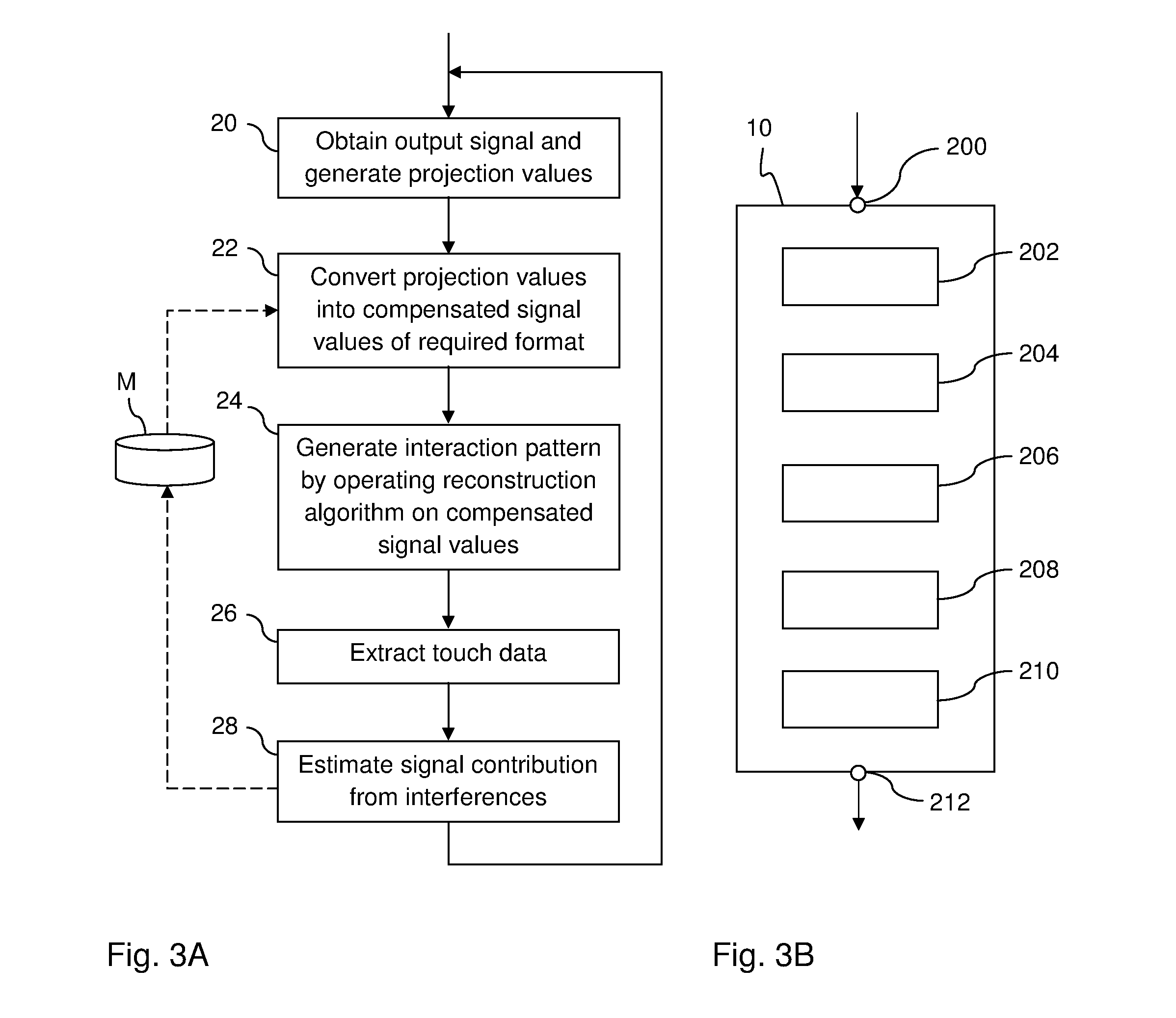
[0052]The present invention relates to techniques for enabling extraction of touch data for multiple objects in contact with a touch surface of a touch-sensitive apparatus. The description starts out by presenting the underlying concept of such a touch-sensitive apparatus, especially an apparatus operating by frustrated total internal reflection (FTIR) of light. The description continues to present embodiments for suppressing the influence of signal interferences in a touch determination process. Finally, detailed examples are given.

[0053]Throughout the description, the same reference numerals are used to identify corresponding elements.

1. Touch-Sensitive Apparatus

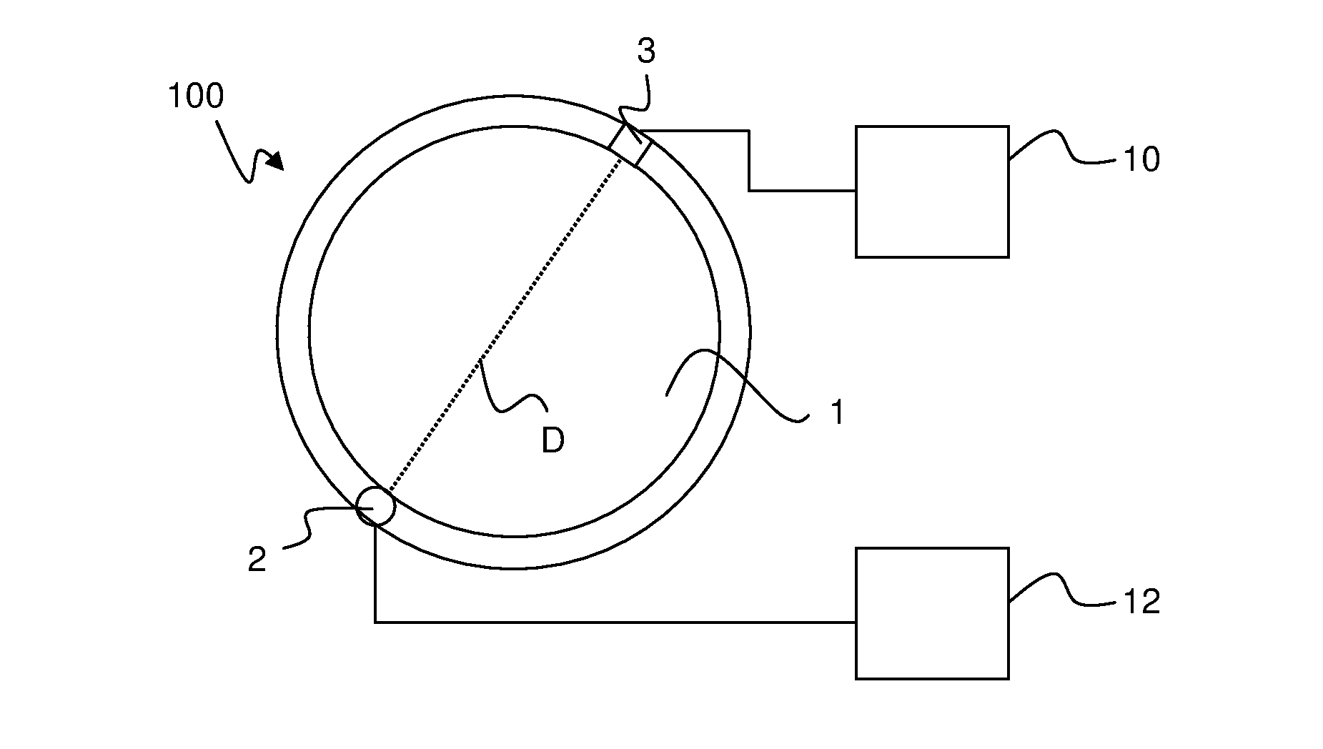
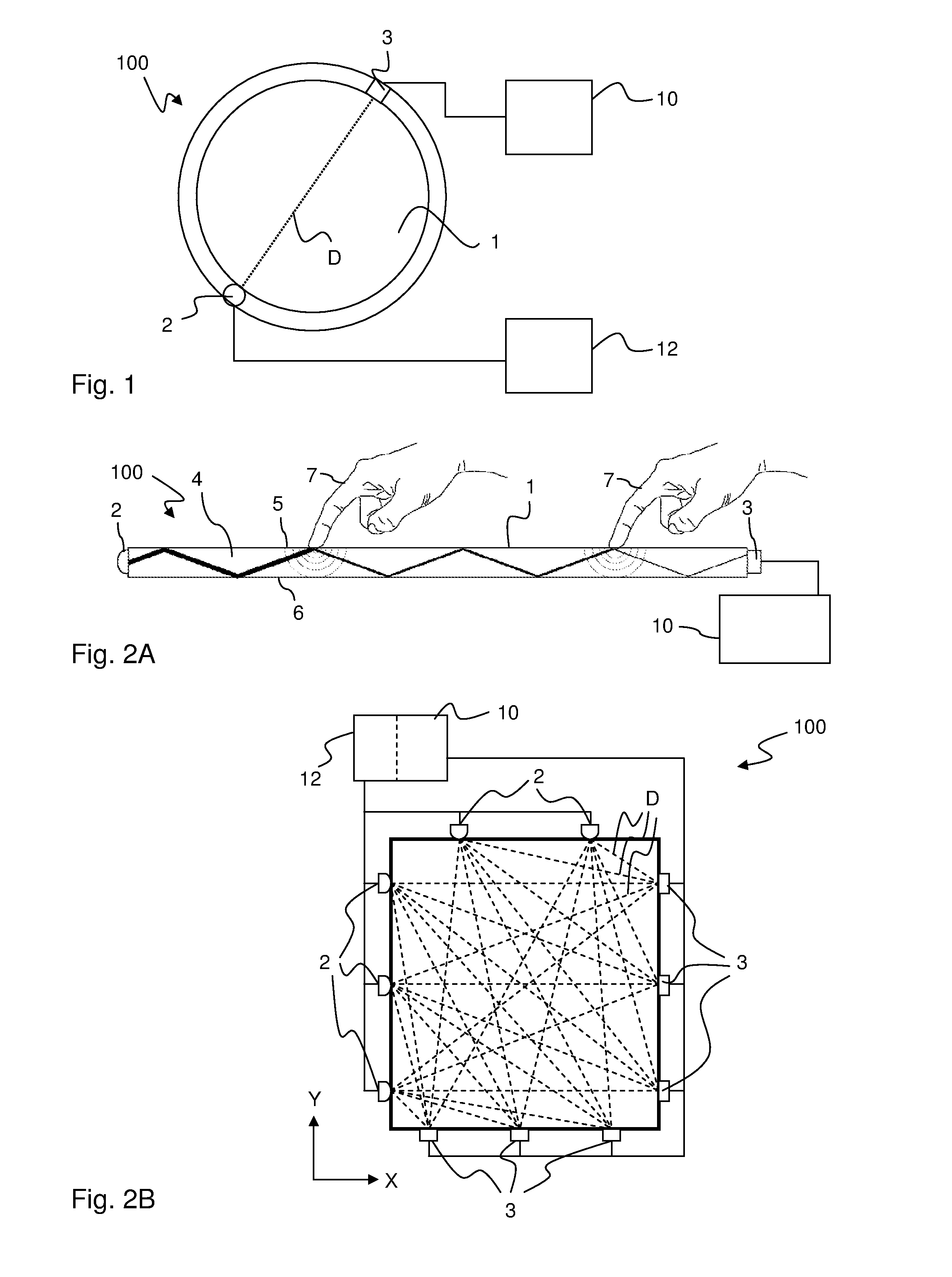
[0054]FIG. 1 illustrates a touch-sensitive apparatus 100 which is based on the concept of transmitting energy of some form across a touch surface 1, such that an object that is brought into close vicinity of, or in contact with, the touch surface 1 causes a local decrease in the transmitted energy. The touch-sensitive appa...


PUM


Abstract

A multi-touch system includes a panel for conducting signals, e.g. by FTIR, from incoupling points to outcoupling points, to define detection lines across the panel. A signal processor operates in a repeating sequence of iterations to obtain an output signal from a detector coupled to the outcoupling points and generate a formatted signal value for each detection line, and operate a reconstruction algorithm on the formatted signal values to determine an interaction pattern on the panel. The signal processor also, at least intermittently in the sequence of iterations, operates compensation data on the formatted signal values to compensate for contaminations on the panel, and calculates updated compensation data based on an interference pattern determined as a function of the interaction pattern, the interference pattern being a 2D representation of contamination-induced signal interferences. The influence of contaminations in the interaction pattern is thereby suppressed.

Description

CROSS-REFERENCE TO RELATED APPLICATIONS[0001]The present application claims the benefit of Swedish patent application No. 1150206-9, filed 9 Mar. 2011, and U.S. provisional application No. 61 / 450,808, filed 9 Mar. 2011, both of which are incorporated herein by reference.TECHNICAL FIELD[0002]The present invention relates to touch sensing systems and data processing techniques in relation to such systems.BACKGROUND ART[0003]Touch sensing systems (“touch systems”) are in widespread use in a variety of applications. Typically, the touch systems are actuated by a touch object such as a finger or stylus, either in direct contact, or through proximity (i.e. without contact), with a touch surface. Touch systems are for example used as touch pads of laptop computers, in control panels, and as overlays to displays on e.g. hand held devices, such as mobile telephones. A touch panel that is overlaid on or integrated in a display is also denoted a “touch screen”. Many other applications are know...

Claims


Application Information

Patent Timeline
IPC IPC(8): G06F3/041
CPCG06F3/0416G06F3/042G06F2203/04808G06F3/04186
Inventor WALLANDER, MATS PETTERCHRISTIANSSON, TOMASWALL, HENRIK
Owner FLATFROG LAB
Why Eureka
Try Eureka