Vision testing device using multigrid pattern

a multi-grid pattern and testing device technology, applied in the direction of instruments, television systems, material analysis, etc., can solve the problems of delay in the height test time, complex calculation process for height testing, and errors in the height test, so as to improve the uniformity of light irradiation

Inactive Publication Date: 2013-12-26
MIRTEC
View PDF3 Cites 9 Cited by
  • Summary
  • Abstract
  • Description
  • Claims
  • Application Information

AI Technical Summary

Benefits of technology

[0013]Accordingly, the present invention has been made to solve the above-mentioned problems occurring in the prior art, and an object of the present invention is to provide a vision testing device capable of exactly calculating the height thereof even though the height of the testing object is high.
[0014]Another object of the present invention is to provide a vision testing device capable of exactly calculating the height thereof and testing it at high speed.
[0015]Further another object of the present invention is to provide a vision testing device capable of improving the uniformity of the light irradiated on the surface of the testing object.

Problems solved by technology

Therefore, these factors can lead to errors in the height test.
In order to eliminate these errors, there are problems in that the calculation process necessary for the height test is complicated and the time necessary for the height test is delayed.

Method used


Image

  • Vision testing device using multigrid pattern
  • Vision testing device using multigrid pattern
  • Vision testing device using multigrid pattern

Examples


Embodiment Construction

[0036]Hereinafter, an exemplary embodiment of the present invention will be described in detail with reference to the accompanying drawings.

[0037]Prior to this, the terms used in the present specification and claims are not limited to the terms used in the dictionary sense. On the basis of the principle that the inventor can define the appropriate concept of the term in order to describe his / her own invention in the best way, it should be interpreted as meaning and concepts for complying with the technical idea of the present invention.

[0038]Thus, though the preferred embodiments of the present invention with drawings have been disclosed for illustrative purposes, those skilled in the art will appreciate that various modifications, additions and substitutions are possible.

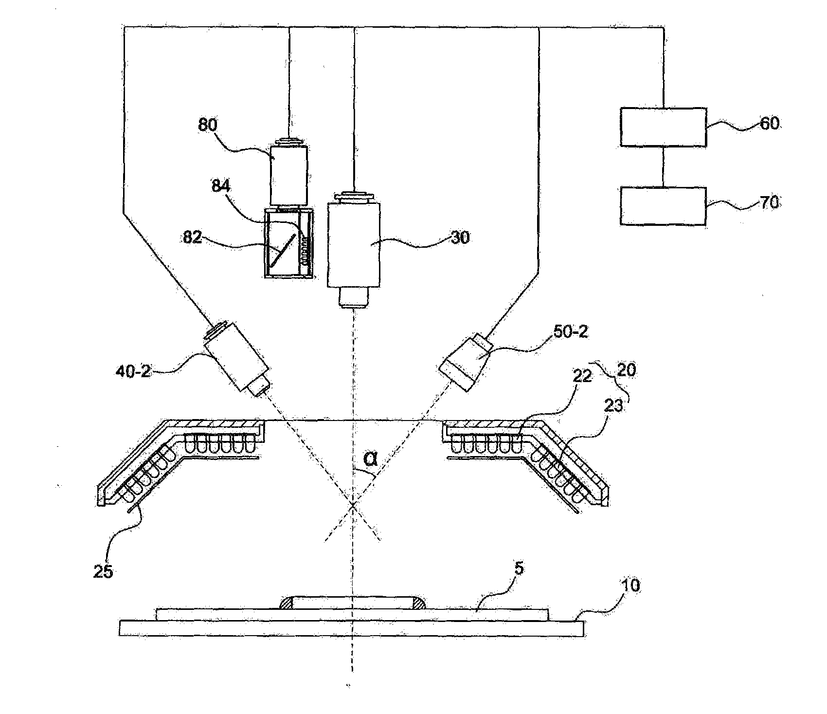
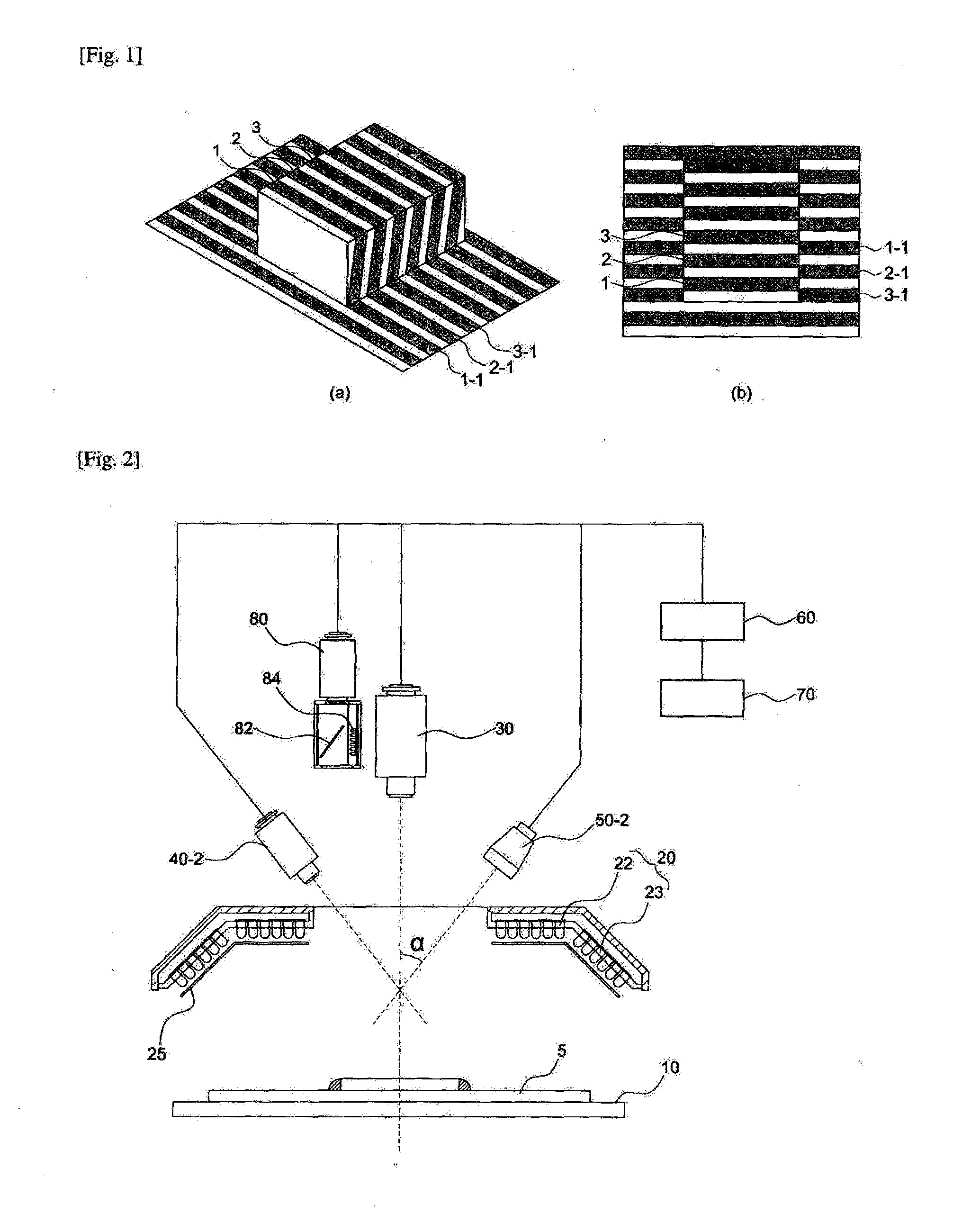
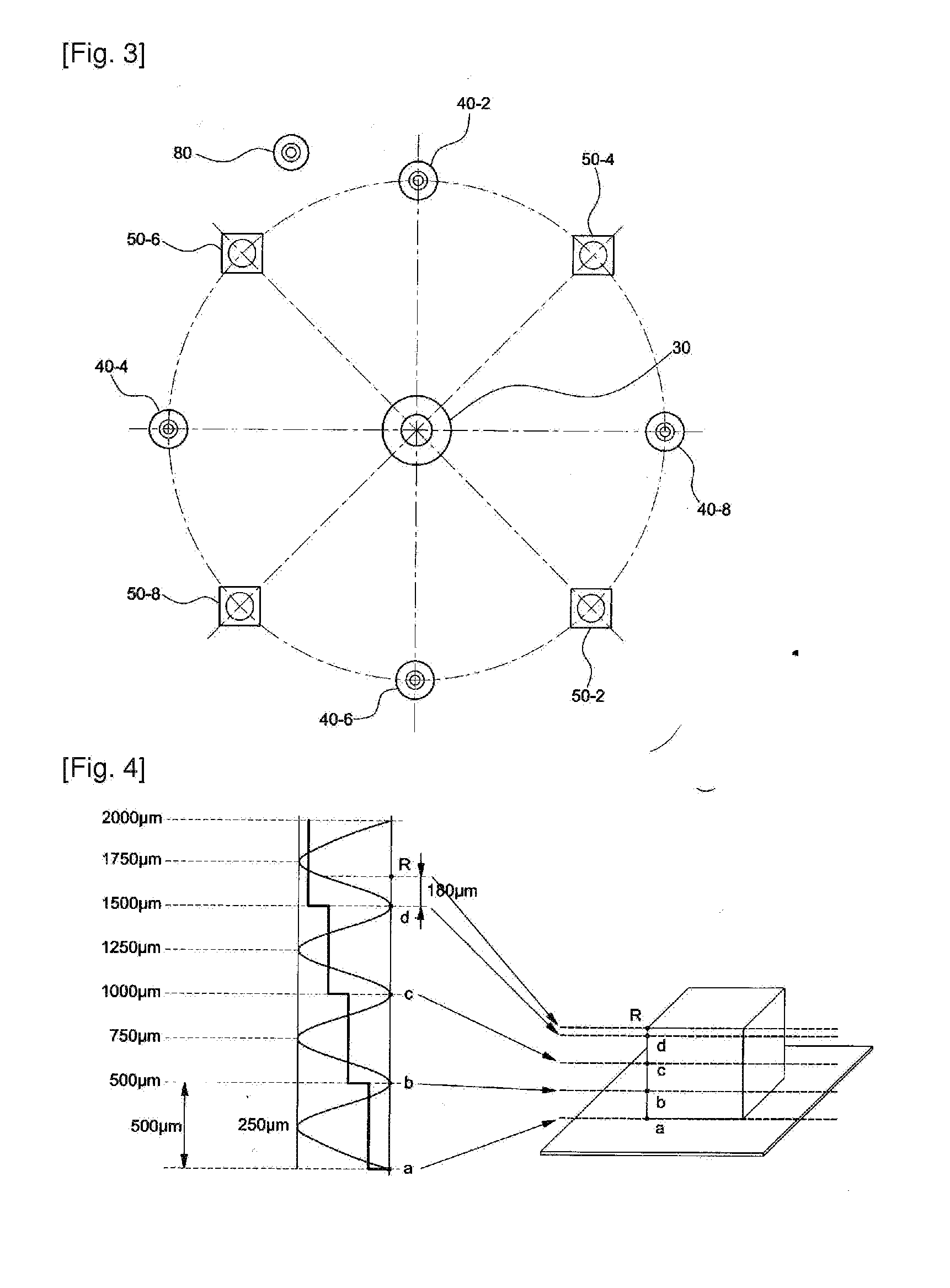
[0039]FIG. 2 is a schematic side sectional view of a vision testing device according to the present invention and FIG. 3 is a schematic planar view of a vision testing device according to the present invention.

[004...


PUM


Abstract

Provided is a vision testing device using a multigrid pattern for determining good or bad of a testing object by photographing the testing object assembled or mounted during the component assembly process and comparing the photographed image with a previously inputted target image, comprising: a stage part for fixing or transferring the testing object to the testing location; a lighting part for providing lighting to the testing object located on an upper portion of the stage part; a center camera part for obtaining a 2-dimensional image of the testing object located in a center of the lighting part; a irradiating part placed on a side section of the center camera part; a vision processing unit for reading the image photographed by the center camera part and determining good or bad of the testing object; and a control unit for controlling the stage part, the grid pattern irradiating part, the center camera part, wherein the grid pattern irradiating part irradiates grid patterns having periods of different intervals.

Description

BACKGROUND OF THE INVENTION[0001]The present invention relates to a vision testing device. More particularly, the present invention relates to a vision testing device in that a vision test is conducted by using a grid pattern of a large period and a grid pattern of a small period, thereby rapidly and accurately measuring the height of the testing object.[0002]In general, a surface mounting technology SMT of assembling a surface mounting components in a printed circuit board and the like includes a technology for miniaturization / integration of a surface mounting device SMD, a development of precision assembly equipments of exactly assembling these surface mount devices, and a technology of operating various assembly equipments.[0003]Typically, a surface mounting line consists of a surface mounting apparatus and an equipment such as a vision testing device. The surface mounting apparatus is an equipment for mounting the surface mounting device on the printed circuit board. Various sur...

Claims


Application Information

Patent Timeline
Patent Type & Authority Applications(United States)
IPC IPC(8): G01B11/06
CPCG01B11/0608G01B11/25G01B11/2509G01B11/2513G01N21/95684G01N2021/95638
Inventor PARK, CHAN WHAOH, SANG MINKIM, SUNG HYUNKOO, JA MYOUNG
Owner MIRTEC
Why Eureka
Try Eureka