Microscope Having an Autofocusing Device and Autofocusing Method for Microscopes

a technology of autofocusing and microscope, which is applied in the direction of microscopes, optics, instruments, etc., can solve the problems of lateral displacement of the location of the sharpest image on the ccd detector, inaccurate autofocusing, and complicating or distorting the evaluation, so as to achieve rapid and precise autofocusing and reduce the degree of error susceptibility

Active Publication Date: 2013-12-26
LEICA MICROSYSTEMS CMS GMBH
View PDF8 Cites 32 Cited by
  • Summary
  • Abstract
  • Description
  • Claims
  • Application Information

AI Technical Summary

Benefits of technology

[0014]The object that presents itself in this context is that of describing a method and an apparatus for au...

Problems solved by technology

Defocusing of the specimen (i.e. a deviation in the Z direction) results in a lateral displacement of the location of the sharpest image on the CCD detector.
Errors in determining the defocusing are thereby caused, resulting in inaccurate autofocusing.
Located in th...

Method used


Image

  • Microscope Having an Autofocusing Device and Autofocusing Method for Microscopes
  • Microscope Having an Autofocusing Device and Autofocusing Method for Microscopes
  • Microscope Having an Autofocusing Device and Autofocusing Method for Microscopes

Examples


first embodiment

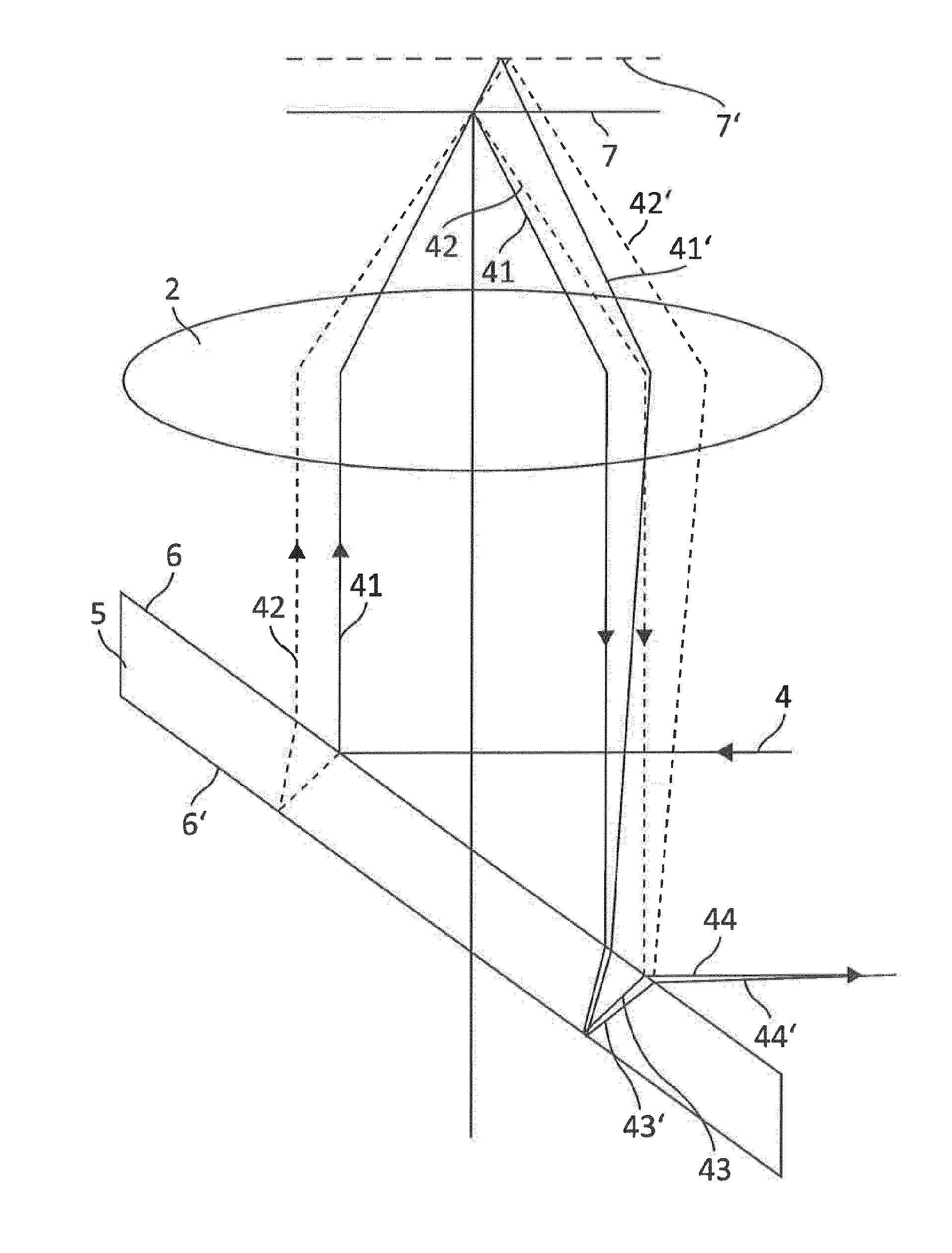
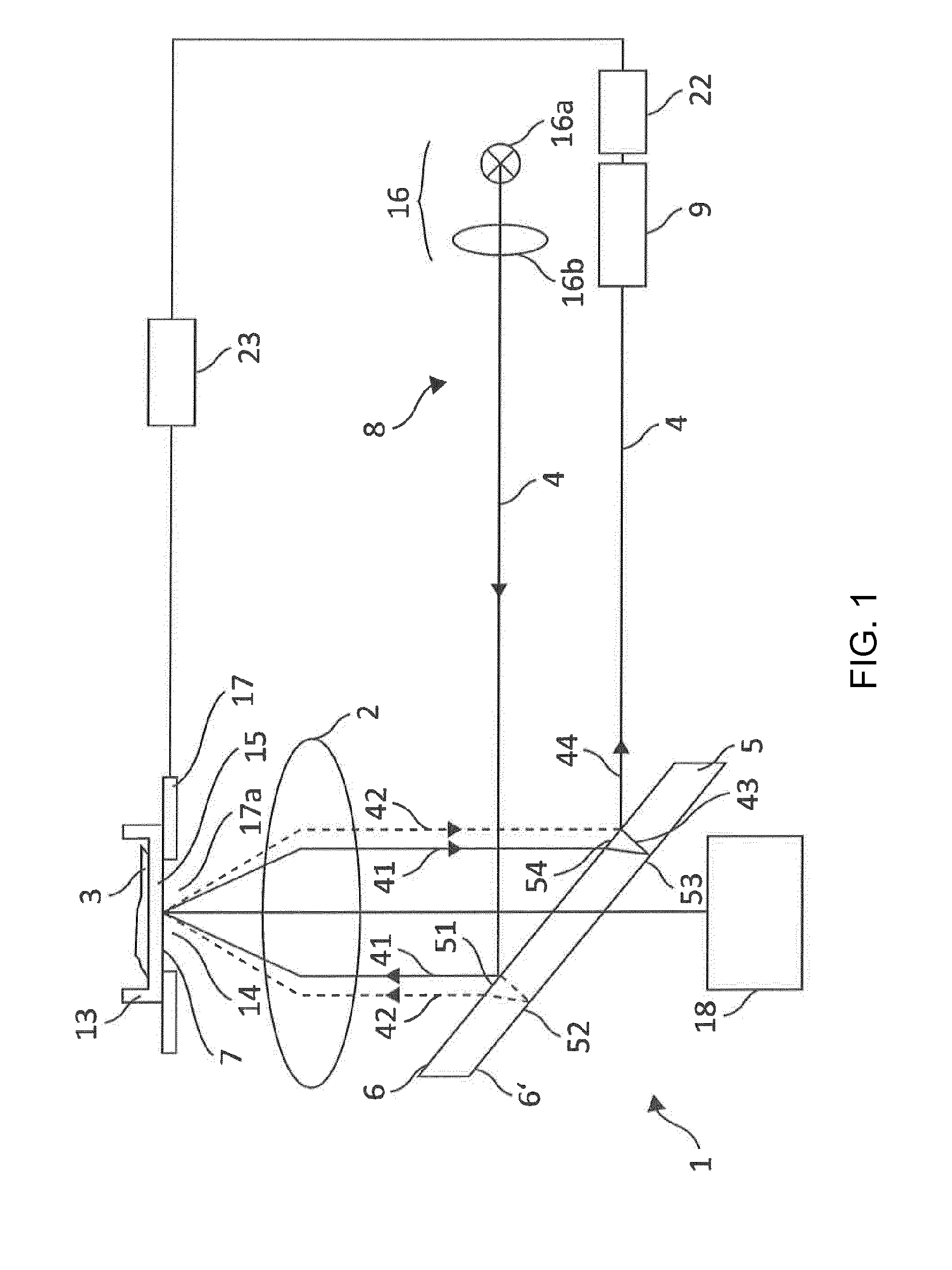
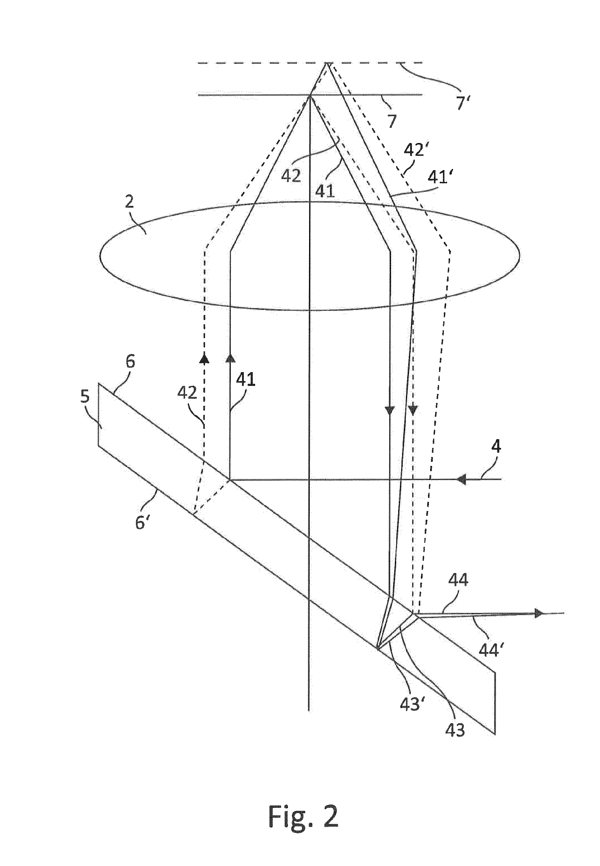
[0079]In a first embodiment, let it be assumed that (proceeding from the depiction in FIG. 1) the two delimiting surfaces 6 and 6′ enclose a wedge angle between them, such that the wedge angle spans a plane (in this case, the drawing plane) in which the outgoing and returning autofocus beam path 4 is located. In such a case, which can easily be illustrated with reference to the depiction in FIG. 1, the sub-beams constituting sub-beam 44 would need to travel along different optical path lengths even in the case of an optimal focus setting, so that an interference stripe pattern at detector 9 would be the consequence. Defocusing in one direction (for example, in a direction away from objective 2) can increase this optical path length difference, while defocusing in the other direction (for example, toward objective 2) can compensate for the optical path length difference present in the focused setting. In the case of compensation, the interference pattern on the detector would disappe...

second embodiment

[0080]In a second embodiment, what is used as deflection device 5 is an optical wedge in which the wedge angle spans a plane that is perpendicular to the drawing plane of FIG. 1, i.e. perpendicular to the plane in which the outgoing and returning autofocus beam path 4 is located. This situation is depicted in FIG. 3. It may be gathered that the configuration depicted in FIG. 3 results in a 90° rotation of the slope of the interference stripes. If it is assumed that in a configuration according to FIG. 1, interference stripes that extend substantially horizontally are produced on the detector surface in the event of defocusing, it is then apparent that what occurs in the case of a configuration according to FIG. 3 is a “baseline” interference in which the interference stripes proceed vertically. The interference stripe orientations described here of course serve only for better elucidation of the effects of using an optical wedge as deflection device 5. It is consequently also possib...


PUM


Abstract

A method for autofocusing in microscopic examination of a specimen located at the focus of a microscope objective uses an autofocus beam path, the autofocus beam path being directed, via a deflection device arranged on the side of the microscope objective facing away from the specimen, toward the microscope objective, and from there onto a reflective autofocus interface in the specimen region. The autofocus beam path is reflected at the autofocus interface and directed via the microscope objective and the deflection device toward an autofocus detector. The deflection device comprises two regions spaced apart from one another in a propagation direction of the autofocus beam path. Each region reflects the autofocus beam path. The autofocus detector is arranged in a plane conjugated with the microscope objective pupil to acquire an interference pattern. The focus of the microscope is adjusted as a function of the acquired interference pattern.

Description

RELATED APPLICATIONS[0001]This application is a Continuation application of International Application PCT / EP2012 / 052097, filed on Feb. 8, 2012, which in turn claims priority to German Patent Application DE 10 2011 003 807.8-56, filed Feb. 8, 2011, both of which are incorporated herein by reference in their entirety.FIELD OF THE INVENTION[0002]The present invention relates to a method for autofocusing, in the context of microscopic examination of a specimen located at the focus of a microscope objective of a microscope, using an autofocus beam path, and to a microscope having a corresponding autofocus device.[0003]In the context of microscopic examination of specimens, it is usual to focus on a “region of interest” in order to obtain a magnified sharp image of that region for examination. It is often necessary to readjust the focus in the course of an examination, for example when living specimens or cells are involved and / or when the optical distance between the objective and the re...

Claims


Application Information

Patent Timeline
IPC IPC(8): G02B21/06
CPCG02B21/06G02B21/006G02B21/242G02B21/244G02B21/245G03F9/7026G03B13/36
Inventor KRUEGER, RALFBAUER, TOBIAS
Owner LEICA MICROSYSTEMS CMS GMBH
Why Eureka
Try Eureka